QN8066
QN8066 FM DSP RX/TX Arduino Library
This library is intended to provide an easy-to-use interface for controlling the QN8066 FM transceiver and receiver.
The primary goal of this Arduino library project for the QN8066 is to simplify the development of robust applications using this device. I hope that hobbyists, electronics technicians, radio amateurs, and others interested in this work will find success in their projects. All the C/C++ functions and methods are documented here.
This library can be freely distributed using the MIT Free Software model. By using or installing this library, you are agreeing to the terms of the MIT license.
Copyright (c) 2024 Ricardo Lima Caratti.
Contact: pu2clr@gmail.com.
About Me
I hold a Master’s degree in Educational Technology from the Federal University of Ceará, where I delved into the ways technology can enhance learning experiences. My passion for computer science led me to specialize in it, focusing on Distributed Systems Development with an Object-Oriented approach, at the University of Brasília. My academic journey began with a Bachelor’s degree in Information Systems from the União Pioneira de Integração Social (UPIS-Brasília). Outside the classroom, my main hobbies are electronics and Amateur Radio.
Notice to Users Regarding this Library
This library is continuously evolving, with both corrective and feature updates. While the implemented functions have been tested, it is possible that in certain situations, the library may exhibit unexpected behavior. I encourage users to always utilize the latest release of this library. Should you encounter any issues, please feel free to contact me at pu2clr@gmail.com. I will do my best to address or clarify any problems as quickly as possible. Thank you.
Contents
- Legal Compliance Guidelines
- QN8066 Arduino Library Features
- Technical Overview of the QN8066 RX/TX Device (IC)
- Why a QN8066 library for Arduino?
- Groups and Forums
- QN8066 Functional Blocks
- QN8066 PINOUT
- QN8066 Summary of User Control Registers
- QN8066 and Arduino based on ATmega328 or LGT8F328
- Homemade setup with the QN8066
- DIY Kit 5W-7W FM Transceiver
- Arduino Library Documentation
- Arduino Sketch examples
- Examples Index
- Boards where this library can be compiled
- Donate
- Most Frequent Problems
- References
Legal Compliance Guidelines
Important Notice
It is important to emphasize that the project presented here is not intended to encourage anyone to violate their country’s regulations regarding radio frequency emissions. The goal of this project, centered around an Arduino library for controlling the QN8066, is to facilitate the development of diverse solutions involving this device.
Please, be aware that the use of FM transmitters is regulated by the laws and regulations of each country. It is crucial to ensure that your use of any FM transmitter complies with the applicable legal requirements and does not violate any broadcasting regulations.
Legal Compliance Guidelines
- Frequency Range: Ensure that the frequency range used by your FM transmitter is permitted in your country.
- Transmission Power: Adhere to the maximum allowed transmission power to avoid interference with licensed broadcasters and other communication services.
- Licensing: Check if a license is required to operate an FM transmitter in your region. Obtain the necessary permissions if required.
- Interference: Avoid causing interference with other electronic devices and communication services. Ensure your setup follows the prescribed technical standards.
- Public Safety: Be mindful of public safety and ensure your use of the FM transmitter does not pose any risks.
By following these guidelines, you can ensure that your use of the FM transmitter respects the laws and regulations of your country and does not result in any legal issues.
Brazilian legislation notes
- Brazilian legislation allows some flexibility for the use of frequencies for research, experimentation, and educational purposes.
- FM transmitters with very low power (up to 0.5 mW) and short range can operate without a license.
- Although amateur radio does not cover the commercial FM band, it is regulated by Anatel and permits transmission experimentation on other frequencies to promote technical learning.
- For educational or field transmissions, special authorization can be requested for specific events, such as science fairs or public demonstrations.
- Experimental transmissions may be allowed in controlled environments, such as laboratories, provided the signal does not exceed the physical boundaries of the location or interfere with other services.
- Microtransmitters or prototypes for short-range testing are tolerated as long as they operate within specific bands or with extremely low power.
- Wireless microphones based on FM transmitters are legal if they comply with designated sub-bands and power limits to prevent interference.
- Community radio stations, limited to 25 watts and a 4 km radius, require licenses granted to non-profit organizations through the Ministry of Communications, with permits valid for 10 years and restrictions on commercial advertising.
Groups and Forums
There is a Facebook group called QN80XX FM Transmitters & Receivers Enthusiasts where the purpose is exchanging experiences with projects based on Quintic QN80XX IC family. You will be welcome there.
Donate
If you find this project useful, consider making a donation so that the author of this library can purchase components and modules for improvements and testing of this library. Click here to donate or use the QR code below.
Acknowledgements
-
Mr. Grazianny Carvalho Tavares - I would like to thank Mr. Grazianny Carvalho Tavares, PU7MGR, for introducing me to the QN8066 and encouraging me to develop this library. Mr. Grazianny also played a crucial role in helping me understand various concepts about FM modulation, audio quality criteria, as well as in testing the fundamental functions implemented in this library using equipment for precise value measurements.
-
I would like to thank Mr. Adam Fabio for his article published in the online magazine Hackaday titled Be Your Own DJ With QN8066 And An Arduino Library.
-
I would like to thank Mr. Gareth Halfacree for his article published in the online magazine hackster.io titled Ricardo Lima Caratti’s Handy Arduino Library Delivers Easy QN8066-Powered FM Radio Projects.
-
Mr. Elionaldo Gomes da Silva, PY2EGS, to share his board Layout project with Nano and LCD
Why a QN8066 library for Arduino?
Technically, no Arduino application strictly requires a library. In some cases, avoiding libraries might even be the right decision. However, there are several compelling reasons to consider using them.
Libraries often simplify the design and maintenance of code, and they can make your projects more portable by implementing the necessary functionality across multiple hardware platforms.
For example, if you want to use an LCD or another display device in a project that monitors temperature and atmospheric pressure, there are many excellent libraries available for Arduino users. These libraries usually include most, if not all, of the features you might need. Re-inventing the wheel by not using a library generally doesn’t make sense—unless you need a feature that no existing library supports. Using a library is often the smarter choice, particularly when it can simplify porting your code to different hardware.
Utilizing a library can reduce programming complexity and enhance the robustness of your application. It simplifies life not only for other developers but also for yourself. You don’t need to be a software engineer to see the value in this. A library is similar to an integrated circuit (IC); while you could manually implement the functionality of many ICs in a circuit, doing so would significantly increase the cost, complexity, size, and potential for failure of your project. Often, it’s better to abstract certain functions inside a ready-made IC. The user only needs to know how to interact with the chip, not how the chip itself is designed.
Finally, if you’re already using libraries to handle the I2C bus (Wire.h), TFT or OLED displays, SPI devices, and Serial UART communication, it makes sense to use a library to manage the QN8066 device as well. The QN8066 Arduino Library can add convenience, development speed, and robustness to your project. Unlike closed-source solutions, this library is open-source, allowing you to learn from and modify the code as needed.
Efficient Use of Libraries in Microcontroller Applications
Among the common myths about using this library alongside others is the assumption that it could significantly increase the final code size, making the application unfeasible for many microcontrollers. However, it is essential to highlight that, although the library contains extensive code, a large portion serves to provide directives to the C/C++ compiler and does not necessarily translate into executable code. Examples include type definitions (typedef), data structures (struct), and unions (union). Additionally, modern compilers and linkers offer powerful optimization features, notably Link Time Optimization (LTO), which eliminates unused symbols and code, ensuring the final binary is lean and efficient. These optimizations, combined with dead code elimination and inlining strategies, reduce the overhead, making the use of complex libraries feasible even in resource-constrained environments.
In light of this, to make the most of your application, it is essential to have a deep understanding of the microcontroller architecture you are working with, as well as the tools you are using, such as the compiler and linker.
See also:
- Inline Functions
- Understanding and Exploiting Optimal Function Inlining
- Inline C++ code in embedded applications
- LLVM Link Time Optimization: Design and Implementation
- What is Link Time Optimization (LTO)
- Link-Time Optimization in GCC: Requirements and High-Level Design
- How to use the typedef struct in C
- Structures, Typedef and Union in C Programming
- Bit Fields in C
QN8066 Arduino Library Features
This library uses the I²C communication protocol and implements most of the functions offered by QN8066 IC from QUINTIC. This library also has primitive functions that make it easier for you to implement commands that may not have been implemented yet. As said before, this library is constantly improving. Check the API documentation before implementing a new function. It is likely that your function is already implemented. See the API documentation for this library.
- Open Source. It is free. You can use, copy, modify, merge, publish, distribute, sublicense, and/or sell copies of the Software. See MIT License to know more.
- Built based on QN8066 Datasheet
- C++ Language and Object-oriented programming. You can easily extend the QN8066 class by adding more functionalities.
- API Documentation. All functions implemented in this library have documentation that can be checked in the source code or at this link
- Available on Arduino IDE (via Manage Libraries). Easy to install and use.
- Cross-platform. You can compile and run this library on most of boards supported by the Arduino IDE (Examples: ATtiny85, boards based on ATmega328 and ATmega-32u4, ATmega2560, ARM Cortex, STM32, Arduino DUE, ESP32 and more).
- Simplifies projects based on QN8066
- A lot of examples to guide the user
- RDS support
- Clock reference selection - The QN8066 has a pin (XCLC) that should be used to inject a signal that will be utilized by the IC as a reference clock. This signal can be 32.768 kHz or a multiple of this value. This library allows you to adapt your project to the active crystal you have available. See below for more details about it.
Technical Overview of the QN8066 RX/TX Device (IC)
Introduction
The QN8066 is a highly integrated and versatile receiver/transmitter (RX/TX) device designed for use in FM radio applications. It offers a comprehensive solution for high-quality audio reception and transmission with minimal external components, making it suitable for a wide range of applications, including portable radios, automotive systems, and multimedia devices.
Key Features
- Frequency Range: The QN8066 operates over a wide frequency range, supporting FM band frequencies from 64 MHz to 108 MHz.
- High Sensitivity: The device is engineered to provide excellent sensitivity, allowing for clear reception of weak signals.
- Integrated Analog and Digital Functions: It includes both analog and digital components, ensuring compatibility with various audio formats and enhancing overall functionality.
- Stereo Decoder: The integrated stereo decoder ensures high-fidelity stereo audio output.
- Low Power Consumption: Designed with power efficiency in mind, the QN8066 is suitable for battery-powered devices, extending operational life.
- Digital Signal Processing (DSP): Advanced DSP capabilities improve signal quality and reduce noise and interference.
- Programmable Interface: The QN8066 offers a flexible, programmable interface, enabling easy integration and customization for specific applications.
Technical Specifications
- Operating Voltage: The device operates at a typical voltage range of 2.7V to 3.6V.
- Current Consumption: It features low current consumption, typically around 20mA during active operation.
- Output Power: The output power is adjustable, catering to different transmission requirements.
- Modulation Modes: Supports various modulation modes including mono, stereo, and digital audio formats.
- Interface: I2C interface for easy communication with microcontrollers and other digital systems.
Applications
- Portable Radios: Due to its compact size and low power consumption, the QN8066 is ideal for portable radio applications.
- Automotive Systems: The high sensitivity and DSP capabilities make it suitable for in-car entertainment systems.
- Multimedia Devices: Compatible with a variety of audio sources, the QN8066 can be integrated into multimedia devices requiring FM reception and transmission capabilities.
QN8066 Functional Blocks
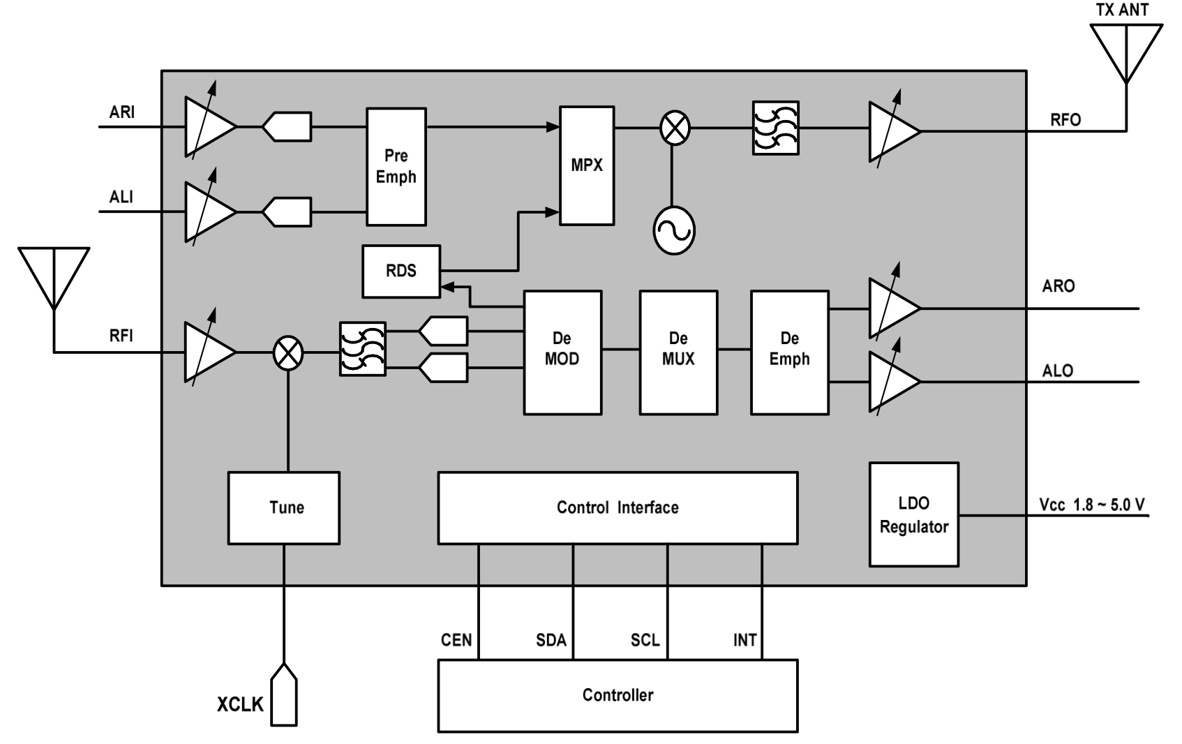
- RF Front-End: The RF front-end is designed to efficiently capture and process FM signals, ensuring minimal loss and high-quality signal reception.
- PLL Synthesizer: The phase-locked loop (PLL) synthesizer ensures stable frequency generation and accurate tuning.
- Audio Processing: Includes both analog and digital audio processing units to enhance sound quality and support various audio formats.
- Power Management: Advanced power management features optimize power consumption, making the QN8066 ideal for portable applications.
Attention
- The Logic signals level of the QN8066 device (CEN, SCL, SDA, to GND) works from 1.6V to 3.6V (see Datasheet, ELECTRICAL SPECIFICATIONS, section Recommended Operating Conditions). If you are using a 5V Arduino board, that Arduino will send 5V signals to the QN8066 device through the digital pins and the I2C bus. That configuration can make the system unstable or damage the QN8066 device. To fix this, use a logic shifter chip that converts between 3.3V and 5V logic.
QN8066 PINOUT
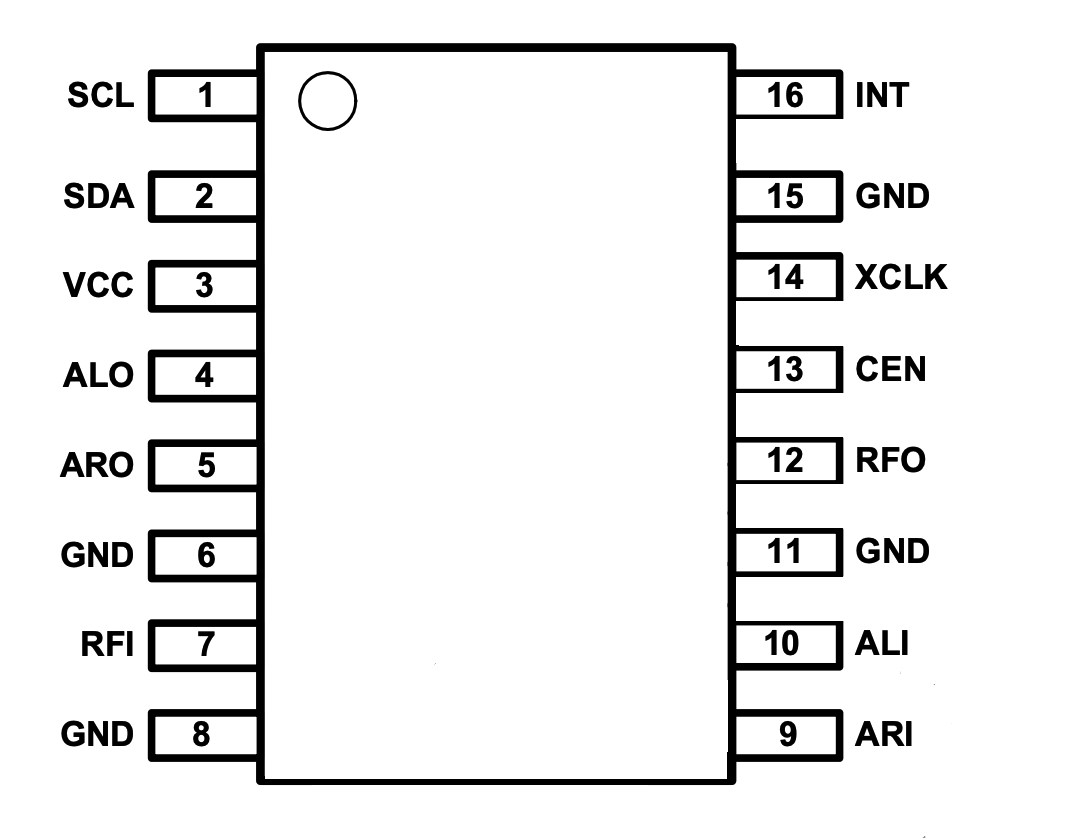
QN8066 Pin Descriptions
| SSOP16 PIN | NAME | DESCRIPTION | |
|---|---|---|---|
| 1 | SCL | Clock for I2C serial bus | |
| 2 | SDA | Bi-directional data line for I2C serial bus | |
| 3 | VCC | Voltage supply | |
| 4 | ALO | Analog audio output – left channel | |
| 5 | ARO | Analog audio output – right channel | |
| 6 | GND | Ground | |
| 7 | RFI | FM Receiver RF input | |
| 8 | GND | Ground | |
| 9 | ARI | Right channel audio input | |
| 10 | ALI | Left channel audio input | |
| 11 | GND | Ground | |
| 12 | RFO | Transmitter RF output – connect to matched antenna | |
| 13 | CEN | Chip enable with internal pull up: Chip power down if less than 0 | 4V and VIO is powered; power up if higher voltage or left floated |
| 14 | XCLK | External clock input | |
| 15 | GND Ground | ||
| 16 | INT | Interrupt output, active low, need pull-up externally |
QN8066 Summary of User Control Registers
| REGISTER | NAME | USER CONTROL FUNCTIONS | |
|---|---|---|---|
| 00h | SYSTEM1 | Sets device modes | |
| 01h | SYSTEM2 | Sets external clock type and CCA parameters | |
| 02h | CCA | Sets CCA parameters | |
| 03h | SNR | Estimate RF input CNR value | |
| 04h | RSSISIG | In-band signal RSSI dBµ V value | |
| 05h | CID1 | Device ID numbers | |
| 06h | CID2 | Device ID numbers | |
| 07h | XTAL_DIV0 | Frequency select of reference clock source | |
| 08h | XTAL_DIV1 | Frequency select of reference clock source | |
| 09h | XTAL_DIV2 | Frequency select of reference clock source | |
| 0Ah | STATUS1 | System status | |
| 0Bh | RX_CH | Lower 8 bit of 10-bit receiver channel index | |
| 0Ch | CH_START | Lower 8 bits of 10-bit channel scan start channel index | |
| 0Dh | CH_STOP | Lower 8 bits of 10-bit channel scan stop channel index | |
| 0Eh | CH_STEP | Channel scan frequency step | Highest 2 bits of receiver channel indexes |
| 0Fh | RX_RDSD0 | RDS data byte 0 | |
| 10h | RX_RDSD1 | RDS data byte 1 | |
| 11h | RX_RDSD2 | RDS data byte 2 | |
| 12h | RX_RDSD3 | RDS data byte 3 | |
| 13h | RX_RDSD4 | RDS data byte 4 | |
| 14h | RX_RDSD5 | RDS data byte 5 | |
| 15h | RX_RDSD6 | RDS data byte 6 | |
| 16h | RX_RDSD7 | RDS data byte 7 | |
| 17h | STATUS2 | Receiver RDS status indicators | |
| 18h | VOL_CTL | Audio volume control | |
| 19h | INT_CTRL | Receiver RDS control | |
| 1Ah | STATUS3 | Receiver audio peak level and AGC status | |
| 1Bh | TXCH | Lower 8 bit of 10-bit transmitter channel index | |
| 1Ch | TX_RDSD0 | Transmit RDS data byte0 | |
| 1Dh | TX_RDSD1 | Transmit RDS data byte1 | |
| 1Eh | TX_RDSD2 | Transmit RDS data byte2 | |
| 1Fh | TX_RDSD3 | Transmit RDS data byte3 | |
| 20h | TX_RDSD4 | Transmit RDS data byte4 | |
| 21h | TX_RDSD5 | Transmit RDS data byte5 | |
| 22h | TX_RDSD6 | Transmit RDS data byte6 | |
| 23h | TX_RDSD7 | Transmit RDS data byte7 | |
| 24h | PAC | PA output power target control | |
| 25h | FDEV | Specify total TX frequency deviation | |
| 26h | RDS | Specify transmit RDS frequency deviation | |
| 27h | GPLT | Transmitter soft chip threshold, gain of TX pilot | |
| 28h | REG_VGA | TX AGC gain |
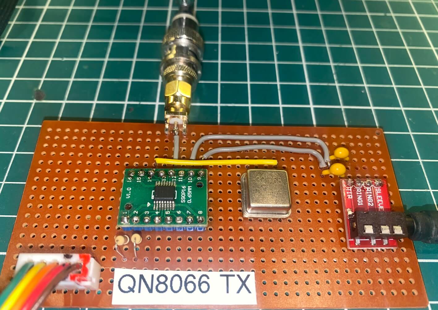
QN8066 and Arduino based on ATmega328 or LGT8F328
The following electrical circuit presents the basic interface configurations of the QN8066 device with an Arduino microcontroller based on the ATmega328 or equivalent, such as the LGT8F328.
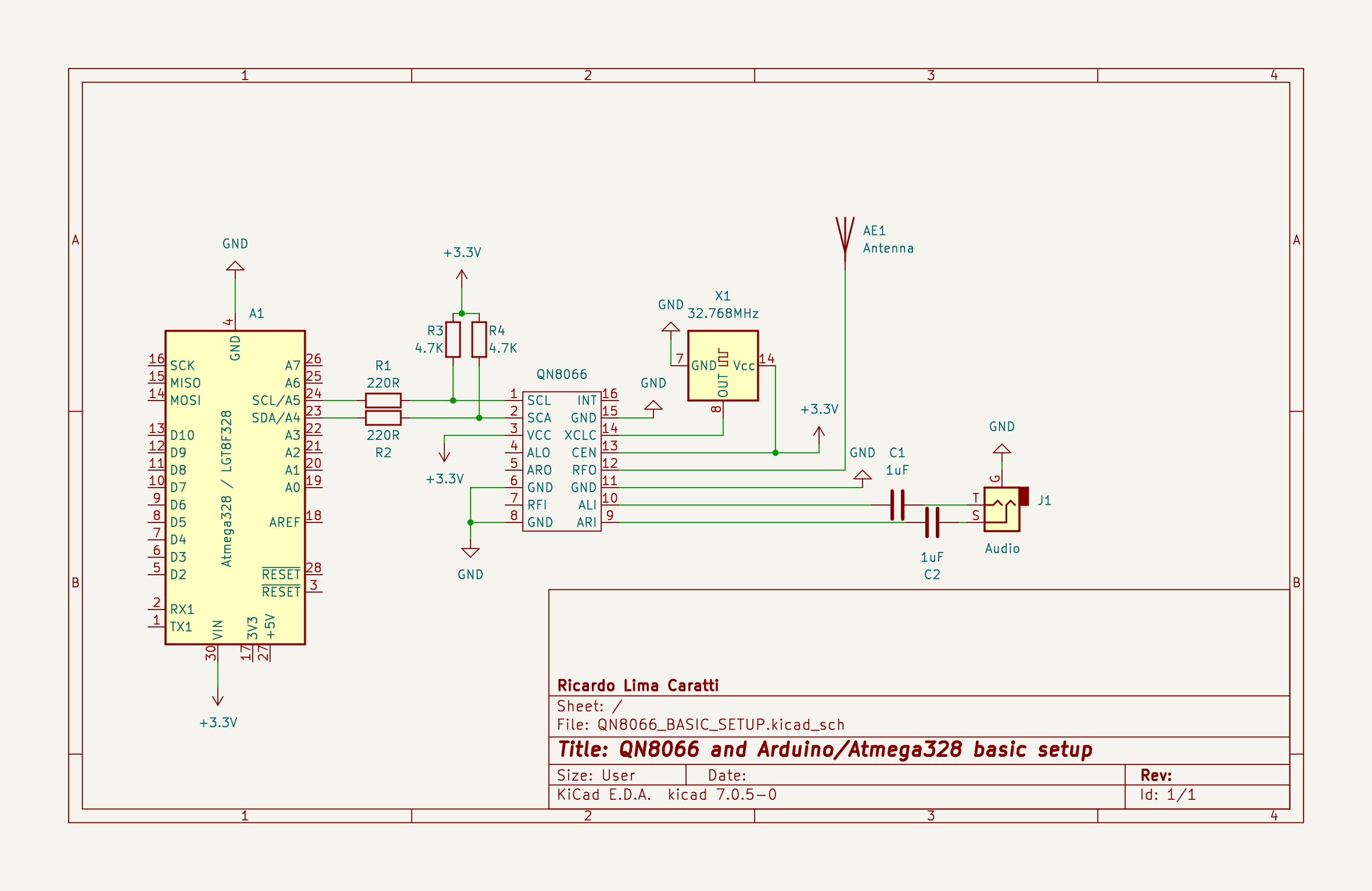
ATTENTION: The QN8066 datasheet specifies a maximum digital interface voltage (SCL, SDA, INT, and CE) of 3.6V. Therefore, it’s recommended to use Arduino boards that operate at 3.3V. In tests conducted by the author of this library, the Arduino Nano, which operates at 5V, worked without issues. However, it’s important to note that this practice is not recommended and may pose a risk of damaging the QN8066. Alternatives include the LGT8F328 (a cheaper Nano-compatible version) and the Arduino Pro Mini (8MHz), both of which operate perfectly at 3.3V. Important: The author of this library is not responsible for any damages that may occur in your experiments based on the information shared in this documentation.
The QN8066 depends on an active crystal (oscillator) for its operation. Although this library is configured for a 32.768 MHz crystal by default, it offers flexibility to accommodate other active crystal or signal generator frequencies. The following section outlines a few oscillator options suitable for the QN8066.
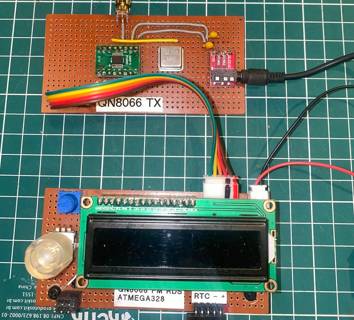
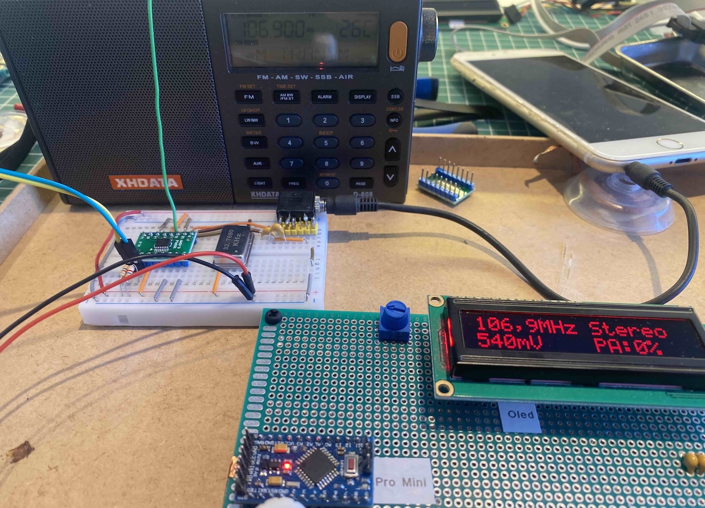
Homemade setup with the QN8066
The following figures illustrate a homemade setup with the QN8066. As you can see, only a few components are needed to build an FM transmitter with the QN8066. The goal here is provide a visual representation of a basic QN8066 circuit assembled on a breadboard. It’s important to note that a 32.768 MHz active crystal is utilized in this particular setup.
The diagram below presents a fundamental setup of the QN8066 interfaced with an ATmega328 microcontroller.
The next prototype uses a 32.768 kHz active crystal, not a 32.768 MHz one. Even with a simpler setup, the circuit worked as expected. Both prototypes demonstrate how few components are needed for this system.
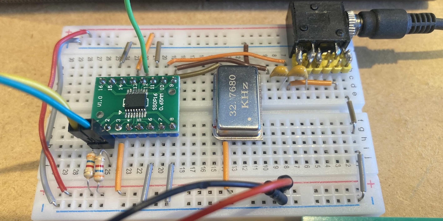
Through some functions in the Arduino library, you can configure the active crystal you intend to use. Check the setup and begin functions for more details.
The table below shows some tested sources (active crystal or signal generator) and divider values.
| Source (kHz) | Divider |
|---|---|
| 32.768 | 1 |
| < 1,310.720 | did not work |
| 1,310.720 | 40 |
| 1,638.400 | 50 |
| 3,276.800 | 100 |
| 13,107.200 | 400 |
| 16,384.000 | 500 |
| 32,768,000 | 1000 |
IMPORTANT: As far as I understand, there is no possibility of using passive crystals. The QN8066 requires an active signal source provided by a generator.
Example 1
/**

This sketch works on Arduino Pro Mini, Nano, UNO, or any other board based on the ATMega328.
IMPORTANT: Refer to the documentation if you are using a 5V microcontroller instead of a 3.3V one.

This sketch illustrates the clock configuration used on the XCLK pin of the QN8066.
Depending on the active crystal or signal generator you are using, it is important
to set the correct frequency and signal waveform type for the QN8066 to function
properly.

IMPORTANT: The QN8066 works with active crystals or signal generators.
           Passive crystals will not work with the QN8066.

Author: Ricardo Lima Caratti (PU2CLR) - 2024
*/

#include <QN8066.h>
#define FREQUENCY 1069 // 106.9 MHz
QN8066 tx;
char str[80];
void setup() {
  Serial.begin(9600);
  while (!Serial) ;
  delay(100); // Wait a bit while the system stabilizes.
  if (!tx.detectDevice()) {
    Serial.println("\nDevice QN8066 not detected");
    while (1);
  }
  // The call to the setup function below illustrates the use of a 32.768 kHz crystal.
  // Since the reference clock for the QN8066 is exactly 32.768 kHz, you can provide the
  // frequency value of the crystal you are using divided by 32.768.
  // For example: if you are using a 32.768 kHz active crystal, then you should provide the
  // divisor value of 1. If the signal generator (active crystal) produces a sine wave,
  // enter the value 0, and if it is a digital signal, you should enter the value 1. See below.
  tx.setup(1,      // Divider based on frequency select of reference clock source. The crystal used here is 32.768 kHz
           false,  // Mono False => TX will start in stereo mode
           false,  // TX will start in RDS OFF
               1,  // PreEmphasis = 75
               1); // 1 if XCLK pin is receiving a digital clock. set it to 0 if you are using a sine-wave oscillator.

  tx.setTX(FREQUENCY);    // Change the FREQUENCY constant if you want another value
  sprintf(str, "\n\nBroadcasting...");
  Serial.print(str);
}
void loop() {
    sprintf(str,"\nFSM: %d\nAudio Peak: %d mV", tx.getFsmStateCode(), tx.getAudioPeakValue());
    Serial.print(str);
    tx.resetAudioPeak();
    delay(15000);
}
Example 2
#include <QN8066.h>
#define FREQUENCY 1069   // 106.9 MHz
QN8066 tx;
char str[80];
void setup() {
  Serial.begin(9600);
  while (!Serial) ;
  delay(100); // Wait a bit while the system stabilizes.
  if (!tx.detectDevice()) {
    Serial.println("\nDevice QN8066 not detected");
    while (1);
  }
  tx.begin();
  // Assuming you are using a 32.768 kHz active crystal, a digital signal, and LO<RF,
  // the image is on the lower side.
  tx.setXtal(1,1,0);
  // tx.setXtal(100,1,0); // If you are using 3,276.8 kHz active crystal
  // tx.setXtal(1000,1,0); // If you are using 32,768 kHz active crystal
  delay(100);
  tx.setTX(FREQUENCY);    // Change the FREQUENCY constant if you want another value
  sprintf(str, "\n\nBroadcasting...");
  Serial.print(str);
}
void loop() {
    sprintf(str,"\nFSM: %d\nAudio Peak: %d mV", tx.getFsmStateCode(), tx.getAudioPeakValue());
    Serial.print(str);
    tx.resetAudioPeak();
    delay(15000);
}
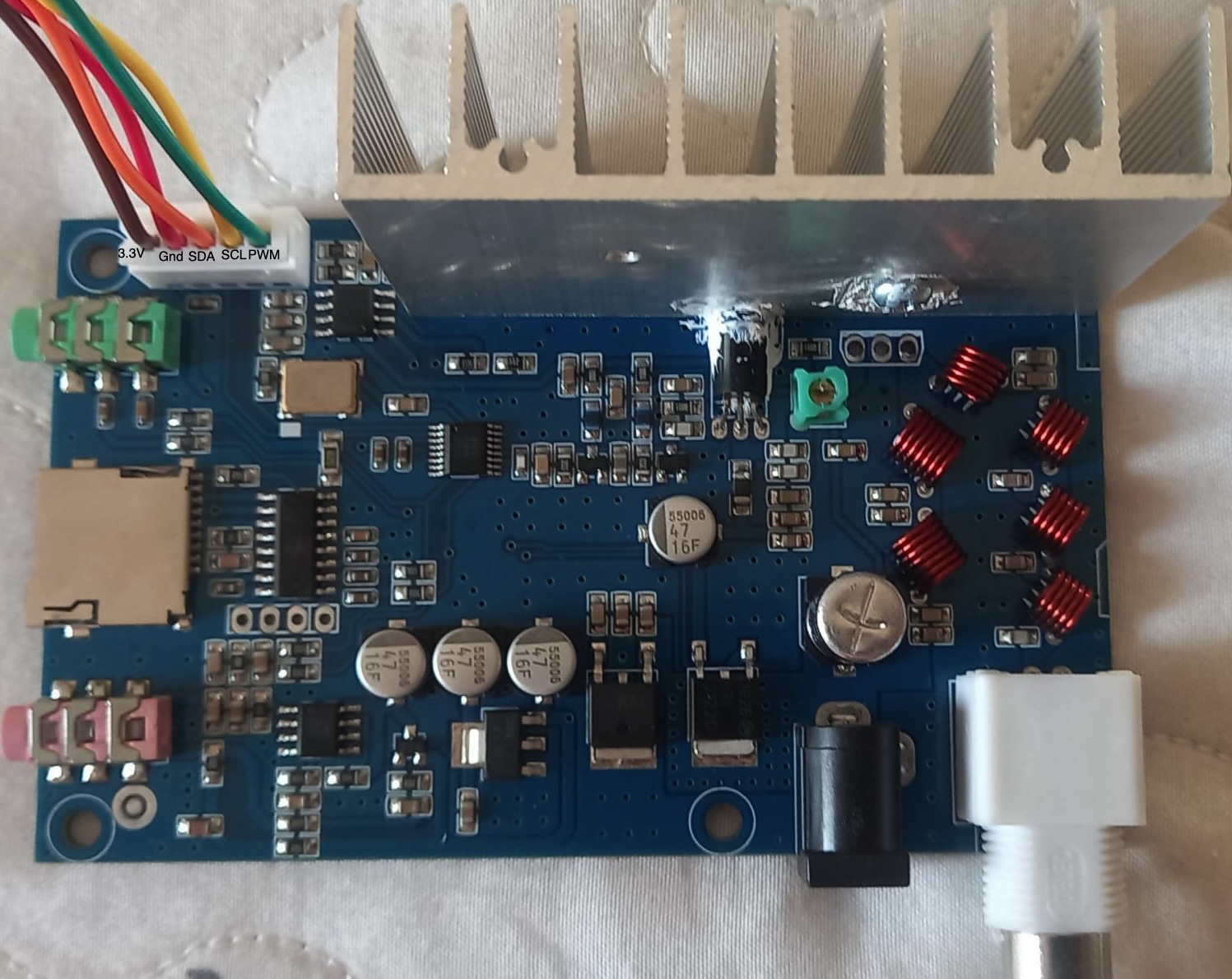
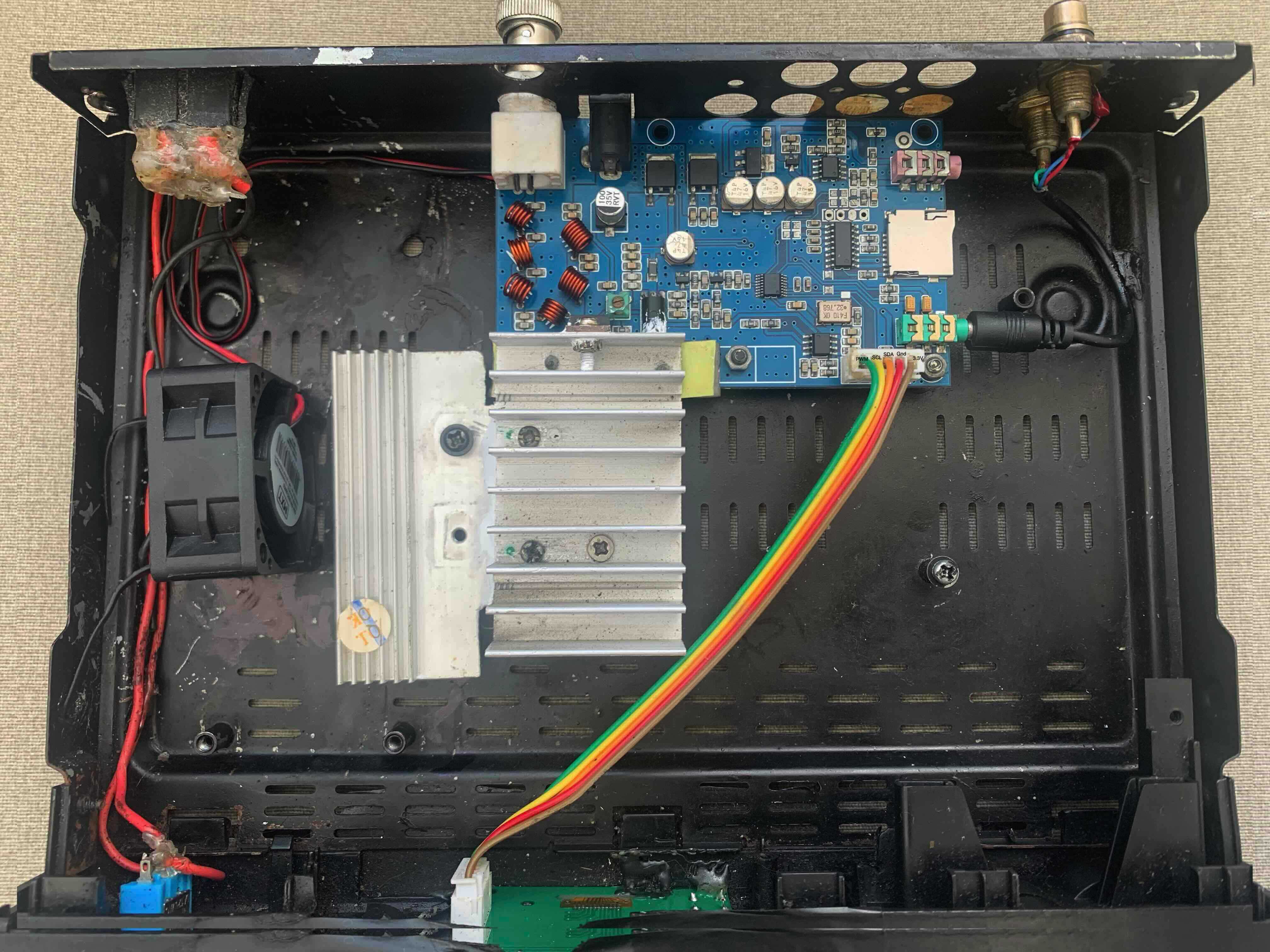
DIY Kit 5W-7W FM Transceiver
It is possible to find transceivers based on the QN8066 in kit form. With this library, you will also be able to control this kit, thereby expanding its original functionalities. Check AliExpress and other sources to find it.
The images below show the DIY Kit 5W-7W FM Transceiver available on AliExpress.
DIY Kit 5W-7W FM Transceiver assembled without the RF final amplifier
DIY Kit 5W-7W FM Transceiver assembled in a homemade case
Using the QN8066 Arduino Library with DIY Kit 5W-7W FM Transceiver
The code below is a minimalist sketch example of using this library with the DIY Kit 5W-7W FM board.
Arduino and the Kit 5W-7W FM connections
| Arduino Nano or Uno pin | Kit 5W-7W FM |
|---|---|
| GND | GND |
| D9 | PWM (*1) |
| A4 | SDA (*2) |
| A5 | SCL (*2) |
(1) Communication Issue During PWM Signal Generation
During experiments, commands sent to the QN8066 via I2C often had no effect, such as switching from “Stereo” to “Mono” or changing the transmission frequency. To resolve this, disable the PWM (0% duty cycle) before sending commands and re-enable it afterward.
#include <QN8066.h>
QN8066 dv;
void setup() {
  Serial.begin(9600);
  while (!Serial);
  pinMode(9, OUTPUT);  // Pin use to PWM power control
  dv.setup();
  Serial.print("\nStarting the system...");
  delay(1000);
  dv.setTX(1067); // Set the transmitter to 106.7 MHz
  dv.setTxStereo(true);
  // Now you can start PWM
  analogWrite(9, 50);  // It is about 1/5 of the max power (5~7W). It is between 1 and 1,4 W
  Serial.print("\nBroadcasting...");
  // Turning the Stereo OFF
  analogWrite(9, 0); // Disable PWM
  dv.setTxStereo(false);
  analogWrite(9, 50); // Enable PWM
}

void loop() {
}
(2) Compatibility Between the KIT and 5V Microcontroller Such as the Arduino Nano
The “DIY 5~7W FM Transmitter Kit” is designed for 3.3V controllers and has I2C pull-up resistors connected to its 3.3V power supply. However, the Arduino Nano operates at 5V, producing 5V signals on the I2C bus, which can cause communication instability. Additionally, the Nano cannot run stably on a 3.3V supply from the kit.
The simplest, but impractical, solution is to modify the Arduino Nano to run at 3.3V by changing its crystal to 8MHz and updating the bootloader. A better option is to use an Arduino Pro Mini 3.3V for direct compatibility.
In some examples using the Arduino Nano, a 3.3V to 5V voltage converter was added for power, along with two 150-ohm resistors in series with the I2C bus and two 10K resistors as pull-ups. While not ideal, this method works. A more appropriate solution would be to use a bidirectional I2C level shifter for compatibility.
The Arduino Nano is used in some examples in this library because it’s popular among hobbyists, many of whom already have one or an Arduino Uno with the same architecture. Most other examples use 3.3V microcontrollers that do not require any modifications.
See also DIY Kit 5W-7W FM example
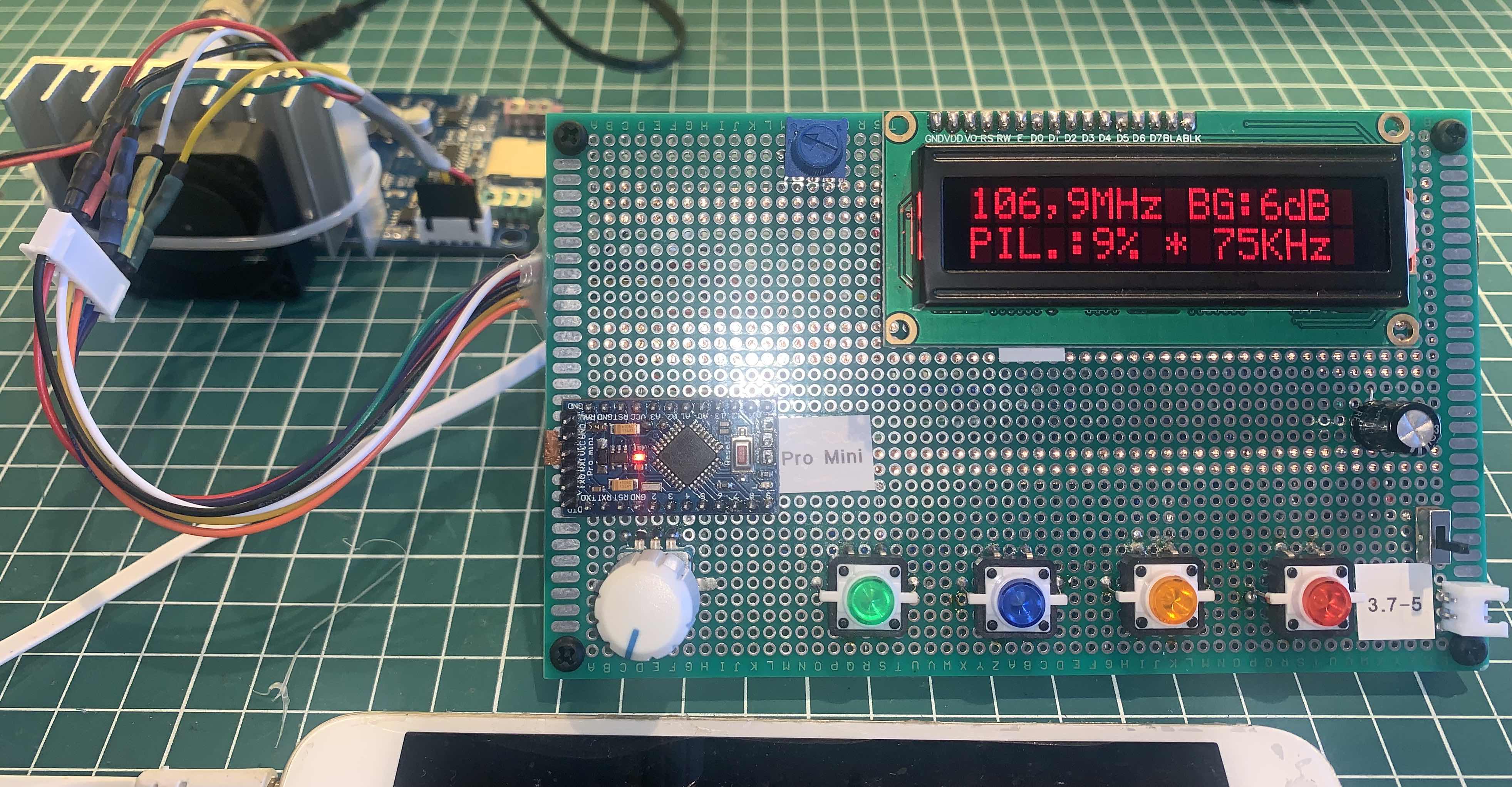
DIY Kit 5W-7W FM connected with Arduino Pro Mini
The following figure shows the “DIY Kit 5W-7W FM TRANSMITTER” connected to the Arduino Pro Mini. The following link provides more operational details. Click here to watch the video.
 Click here to see the source code and schematic
Some personal considerations about this KIT
Before presenting some observations that I consider important, it is worth highlighting that the following information may not reflect the reality in other environments or with other kits. The goal here is not to judge the quality of the kit or its architecture. However, these observations may explain some phenomena you might experience during the development of your project and help you mitigate these issues.
Based on several experiments I conducted with this kit, I observed instability in the communication between the microcontroller and the QN8066 via the I2C bus in the following situations:
-
PWM Line Interference: When the PWM line to control the transmitter’s power is active, communication failures and even unavailability of the QN8066 to respond to new commands are common. One solution to this problem was to disable the PWM signal every time a command is sent to the system and re-enable the PWM signal afterward. It is important to note that this behavior hinders or limits, to some extent, a more dynamic use of RDS services.
-
High Power Transmission: When the transmitter is configured to transmit at higher power levels, approaching its upper limit of 7W, the communication also becomes unstable, and the QN8066 stops responding to the microcontroller, even though it continues to transmit.
-
Avoid touching: Touching certain points on the KIT board or the microcontroller with your hands can also cause system instability.
-
Wire-up organization: Shortening and organizing the I2C bus lines that connect the KIT to the microcontroller significantly improves system stability.
-
Good grounding: Through good grounding, it was possible to make the system more stable.
-
System Stability of the KIT Powered via Microcontroller (Tests and Results): Without using the power module, that is, by only powering the QN8066 stage of the board through the interface connector with the microcontroller, the system remains stable. The example sketches provided in this library ran for hours without any instability. The sketch developed for the Arduino Pro Mini and LCD16x2 was subjected to a test lasting over 16 hours without any issues.
-
Impact of RF Interference on I2C Communication in Power Control Systems: There is another point to consider that might somewhat absolve the issue of power control via I2C. As the bandwidth increases, the transmitter’s power also rises. It’s possible that excessive RF signal in close proximity to the circuit is disrupting the I2C communication. When using a “dummy load,” there is a noticeable reduction in I2C communication errors. This can be demonstrated by eliminating the I2C control and manually controlling it by applying a voltage of 3.3V or lower to the power control line. In my experiments, the I2C communication errors persisted, causing system instability.
-
Enhancing System Stability Through Shielding and Isolation (Future Testing Considerations): Finally, I believe that good shielding of the KIT in a metal enclosure, as well as isolating the microcontroller from the transmitter (in a separate enclosure), could significantly improve the system. This is something to be tested in the future.
The following are some references to reports that may align with what was previously mentioned.
It is important to highlight that this library was not developed exclusively to work with this kit. In fact, it was designed to work with any architecture involving the QN8066 via the I2C protocol. That said, it is crucial for the designer or experimenter to keep in mind the necessary precautions to provide a stable system. There are various literatures that can help follow the best design practices involving I2C communication.
Considerations
In a new project involving the QN8066, I believe a more stable approach would be not to work with power levels above ½W on the same board. An additional amplification module could be added separately from the QN8066 circuit. The organization of the printed circuit board is also a determining factor in improving the stability of the system. Preferably, the communication circuit of the microcontroller with the QN8066 should be as far away as possible from the RF circuit. The appropriate values for the pull-up resistors for the I2C bus is a variable that deserves attention. These values may depend on the length of the bus and other I2C devices that may be connected to the circuit. In my experiments, I used 10K pull-up resistors. However, lower resistance values can be tested and may further improve the stability of the system. Consider shielding the Display and microcontroller circuit so that unwanted signals and interference do not propagate to the QN8066 circuit.
Examples Index
This library includes a comprehensive collection of examples demonstrating various applications and configurations of the QN8066 FM transceiver. The examples are organized by hardware platform and functionality to help you quickly find the most suitable starting point for your project.
Transmitter Examples
1. Basic TX Examples (Serial Monitor)
Basic FM transmitter examples that demonstrate fundamental operations using the Serial Monitor for control and feedback.
- Device Detection - Simple device detection and basic setup
- Minimalist TX - Simplest possible FM transmitter implementation
- Basic TX with Full Setup - Complete basic transmitter with all features
- Advanced TX Control - Enhanced transmitter with advanced control options
- Crystal Clock Setup 1 - Configuration for different crystal frequencies
- Crystal Clock Setup 2 - Alternative crystal configuration methods
2. RDS Transmitter Examples
Examples demonstrating Radio Data System (RDS) functionality for enhanced FM broadcasting.
- RDS Basic Implementation - Basic RDS transmission with Program Service and Radio Text
- Advanced RDS Features - Extended RDS functionality and dynamic content
- RDS with Real-Time Clock - RDS with date/time using DS1302 RTC module
3. LCD Display Transmitter Examples
Complete FM transmitter projects with LCD display interfaces for user-friendly operation.
- Arduino Minimalist LCD - Simple LCD-based transmitter
- Arduino Full LCD Interface - Complete LCD transmitter with encoder control
4. Nokia Display Examples
FM transmitter with Nokia 5110 display for compact, low-power applications.
- Basic Nokia Display - FM transmitter with Nokia 5110 LCD
5. OLED I2C Display Examples
Modern OLED display implementations for high-contrast, easy-to-read interfaces.
- Basic OLED Transmitter - FM transmitter with SSD1306 OLED display
Microcontroller-Specific Examples
6. ATtiny8x Examples
Compact implementations for resource-constrained ATtiny microcontrollers.
- ATtiny24 Transmitter - Ultra-compact FM transmitter
- ATtiny44 with RDS and OLED - Advanced features in minimal footprint
- ATtiny85 with RDS and OLED - Maximum functionality in smallest package
7. ESP32 Examples
Wi-Fi enabled transmitter applications with web interfaces and IoT capabilities.
- ESP32 with LCD and Encoder - Traditional interface with Wi-Fi capability
- ESP32 Web Wi-Fi Control - Web-based transmitter control over Wi-Fi
- ESP32 Python Wi-Fi Interface - Python API for transmitter control
- ESP32 Access Point Portal - Standalone access point with web interface
8. STM32 Examples
High-performance implementations for STM32 ARM Cortex-M microcontrollers.
- STM32 with Encoder and LCD - Professional-grade transmitter control
9. ESP8266 Examples
Cost-effective Wi-Fi solutions for remote transmitter control.
- ESP8266 Access Point Web - Web interface via access point
10. Arduino Nano 33 IoT Examples
Modern Arduino with built-in Wi-Fi connectivity for IoT applications.
- Nano IoT with Encoder and LCD - Traditional control with IoT capability
- Nano IoT Socket Interface - TCP socket communication with Python client
- Nano IoT Web Service - Web-based transmitter control
11. Raspberry Pi Pico Examples
Examples for the popular RP2040-based development board.
- Basic Pico Transmitter - Simple FM transmitter for Pico
- Pico with LCD and Encoder - Full-featured transmitter interface
Receiver Examples
12. Basic Receiver Examples
FM receiver implementations with serial monitor interface.
- Basic RX Implementation - Simple FM receiver with serial control
13. ESP32 Receiver with LCD
ESP32-based FM receiver with LCD display and rotary encoder control.
14. ATmega328 Receiver with LCD
Traditional Arduino Nano/Uno FM receiver with LCD interface.
Utility and Development Tools
15. Development Tools
Useful utilities for development and testing.
- RTC DS1302 Tools - Real-time clock configuration utilities
- STM32 RTC Tools - STM32 internal RTC configuration
16. Test Examples
Various test implementations and experimental code.
- ATmega328 Tests - Hardware compatibility tests
- 3-Button LCD Interface - Alternative control interface
- Encoder LCD without RDS - Simplified encoder interface
- Pro Mini with RTC - Real-time clock integration
17. Under Construction
Experimental and work-in-progress examples.
Access Point Examples for Remote Control
The following examples demonstrate Access Point functionality for standalone operation without requiring external Wi-Fi networks:
- ESP8266 Access Point Web - Creates “ESP8266_QN8066” network (password: 12345678), access via 10.0.0.2
- ESP32 Web Active Portal - Creates “ESP32_QN8066” network (password: esp32qn8066), access via 10.0.0.1
- Nano 33 IoT Web Service - Creates “QN8066” network (password: qn8066123456), web interface at 10.0.0.1
- Nano 33 IoT Socket - Creates “Nano33IoT_QN8066” network (password: 12345678), Python socket communication on port 8066
Getting Started Recommendations
For Beginners:
- Start with Minimalist TX for basic understanding
- Try Basic OLED Transmitter for a simple display interface
For Arduino Users:
- Use Arduino Full LCD Interface for complete functionality
- Try Arduino Nano 33 IoT examples for Wi-Fi capability
For IoT Applications:
- Explore ESP32 Examples for advanced Wi-Fi features
- Use Access Point examples for standalone operation
For Low-Power Applications:
- Check ATtiny8x Examples for minimal power consumption
- Consider Arduino Pro Mini examples running at 3.3V
Build and Compilation Tools
The examples folder also includes automated build tools:
- compile.sh - Linux/macOS compilation script for all examples
- compile.bat - Windows compilation script for all examples
- setup_libraries_boards.sh - Automated setup for Linux/macOS
- setup_libraries_boards.bat - Automated setup for Windows
Most Frequent Problems
- Avoid using a computer connected to the mains during testing. The electrical grid can disturb the communication between the Arduino based board and the QN8066 device.
- Check the I2C bus pull-up resistors.
- Check the voltage on the digital pins of the QN8066. It is not be greater than 3.6V.
- If you are using the Arduino Pro Mini 3.3V (8MHz), check the correct board on Arduino IDE Tools menu, Processor: “Atmega328P (3.3V, 8MHz)”. By default, the Arduino IDE uses the Pro Mini 5V processor version.
- Do not try to power an ATmega328 Arduino Board designed to work with 5V and 16MHz with a 3.3V supply. That configuration will make your system unstable. See ATmega328P Datasheet.
- Do not try to power your Arduino based board designed to work with 3.3V with greater voltage. See the technical specifications of your Arduino Board and remember that the maximum voltage of the QN8066 digital interface is 3.6V.
- During the implementation of your sketch, do not use high power (above 1/2 W) through an RF amplifier without proper shielding practices. The QN8066, particularly the I2C bus, is sensitive to spurious RF signals and may lose communication with the controller. Preferably, use a dummy load.
- Avoid using long wiring for the I2C connection.
- Good grounding: Through good grounding, it was possible to make the system more stable.
References
- Be Your Own DJ With QN8066 And An Arduino Library
- Best Practices for RDS Subcarrier Injection
- Bit Fields in C
- Broadcasting Audio Processing
- Data Sheet - QUINTIC QN8066 Digital FM Transceiver for Portable Devices
- Dynamic_RDS - FM Transmitter Plugin for Falcon Player
- How to use the typedef struct in C
- Inline C++ code in embedded applications
- Inline Functions
- Link-Time Optimization in GCC: Requirements and High-Level Design
- LLVM Link Time Optimization: Design and Implementation
- NATIONAL RADIO SYSTEMS COMMITTEE NRSC-G300-A Radio Data System “RDS” Usage Guideline April 2014
- Old Version of this library - Source 1
- Old Version of this library - Source 2
- Radio Data System
- RDS Encoder Version 1.5 Implementation Manual
- Ricardo Lima Caratti’s Handy Arduino Library Delivers Easy QN8066-Powered FM Radio Projects
- Structures, Typedef and Union in C Programming
- UNIVERSITY COLLEGE LONDON Department of Electronics and Electrical Engineering
- Understanding and Exploiting Optimal Function Inlining
- What is Link Time Optimization (LTO)
- FM Transmitter Remotely Controlled Via ESP32
- FM Transmitter Remotely Controlled Via ESP32