ESP32 and Si4735 Arduino Library
This folder shows some examples with Si4735 Arduino Library and ESP32 platform.
Tips to use ESP32 with Arduino:
Before starting compiling ESP32 based sketches, you must configure your Arduino IDE. Follow the steps below:
- Install the last version of Arduino IDE
- Configure the ESP32 on Arduino IDE
- Open the Arduino IDE and select the Preferences… menu item.
- Go to Additional Boards Manager URLs: and add the URL: https://raw.githubusercontent.com/espressif/arduino-esp32/gh-pages/package_esp32_index.json
- After adding the ESP32 URL, go to Tools menu, select the Boards item and then select Boards Manager… option. Finally install ESP32 board.
- Install the PU2CLR SI4735 Arduino Library
- Go to Tools menu and select Manage libraries…. Finally install the PU2CLR SI4735 Arduino Library.
- Before compiling, select the ESP32 Board on Arduino IDE. Go to Tools menu and select Board item. Then, select ESP32 Arduino. Finally, select “ESP32 Dev Module” or your specific ESP32 board. You need to know what ESP32 board you are using.
- If you are using other versions of the ESP32 (ESP32S3, ESP32C3 etc), please check its pinout before. In general the pin setup are not the same shown here.
If you use the arduino-cli, you can follow the steps below:
$ arduino-cli config set board_manager.additional_urls https://raw.githubusercontent.com/espressif/arduino-esp32/gh-pages/package_esp32_index.json
$ arduino-cli core update-index
$ arduino-cli core install esp32:esp32
Example SI47XX_01_ESP32_AM_FM_TOUCH_SERIAL_MONITOR
This sketch uses just the Serial Monitor as the human interface to test and validation of the SI4735 Arduino Library on ESP platform. It can be very useful to test your circuit.
The main advantages of using this sketch are:
- It is an easy way to check if your setup is working
- You do not need to connect any display device to make your radio works
- You do not need connect any push buttons or encoders to change volume and frequency
- The Arduino IDE is all you need to control the radio
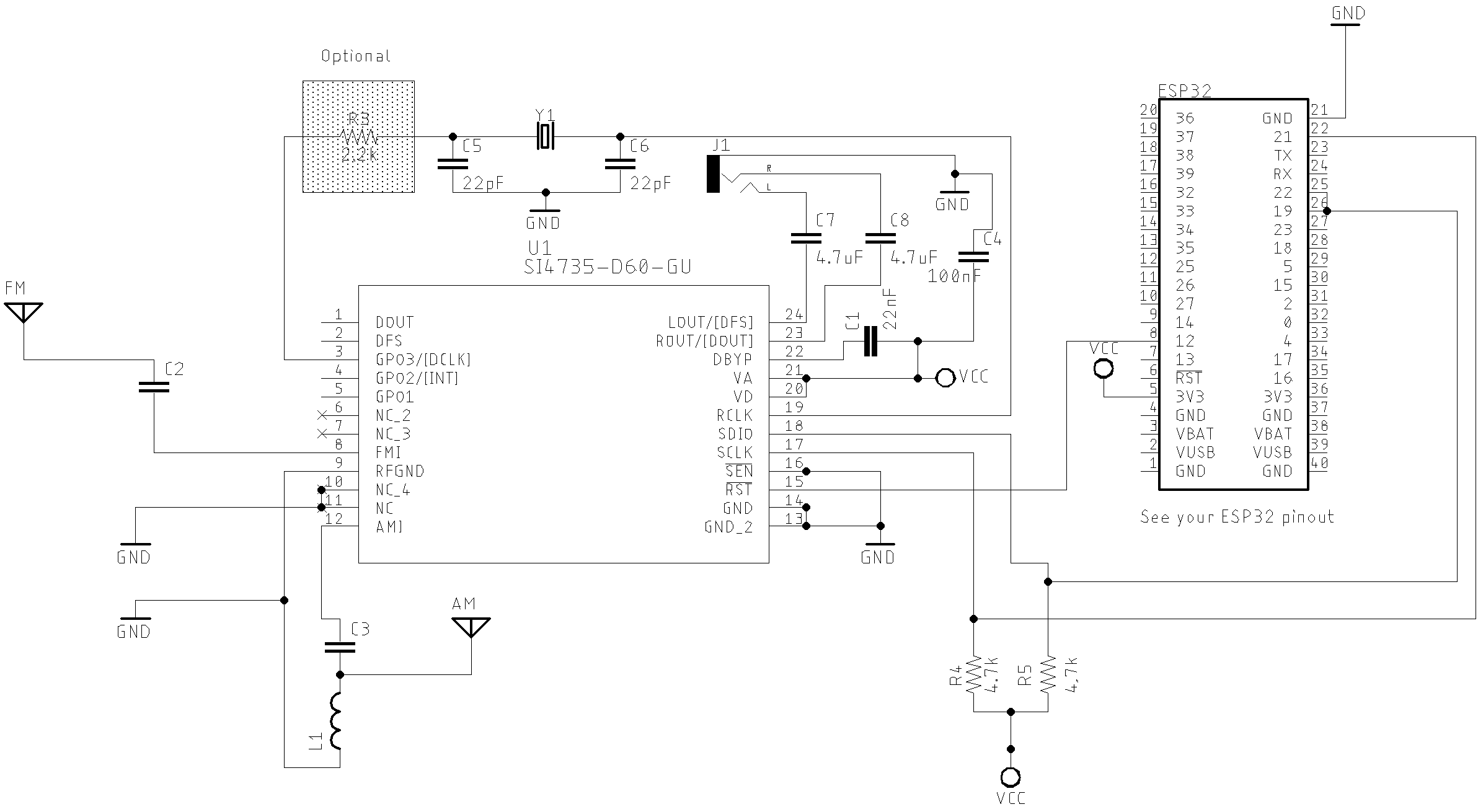
SI4732 / SI4735 Wire up
ESP32 and SI4735-D60 or SI4732-A10 wire up
| Si4735 | SI4732 | DESC. | ESP32 (GPIO) |
|---|---|---|---|
| pin 15 | pin 9 | RESET | 12 (GPIO12) |
| pin 18 | pin 12 | SDIO | 21 (SDA / GPI21) |
| pin 17 | pin 11 | SCLK | 22 (SCL / GPI22) |
Example SI47XX_02_ESP32_TOUCH_ALL_IN_ONE
This example is a complete FM/AM/LW/SW (with SSB support) receiver based on SI4735 running on ESP32
About SSB support
The PU2CLR SI4735 Arduino Library implements a set of methods to apply patches and deal with SSB mode. All documentation about pathces can be seen here.
First of all, the SSB patch content is not part of this library. The patches used here were made available by Mr. Vadim Afonkin on his Dropbox repository. The author of this library does not encourage anyone to use the SSB patches content for commercial purposes. In other words, while this library supports SSB patches, the patches themselves are not a part of this library.
Read more about PU2CLR SI4735 Arduino Library SSB support
ESP32 considerations
The ESP32 has a great resource to interact with system. Instead of buttons, you can use the capacitive sensors available on ESP32 board family.
The ESP32 is a 3.3V part. Pay attention on your I2C LCD device voltage. If it is not 3.3V, the system cannot work properly.
The ESP32 board has enough RAM memory to support all SSB patch and a nice TFT Display library. Consider this feature to improve your sketch.
Schematic
You can use the same schematic used on Arduino family. However, you have pay attention to the new configuration pins on ESP32. See tables bellow. The circuit below shows a generic setup for ESP32. It is very important to consider the pinout of your ESP32 board.
ESP32 basic setup
ESP32 DEVKIT with OLED and Encoder setup
ESP-LOLIN32-WEMOS touch capacitive
| GPIO | Used as | Constant number (#define) | Function Description |
|---|---|---|---|
| GPIO32 | Capacitive | 32 (GPIO32) | Switch MODE (Am/LSB/USB) |
| GPIO33 | Capacitive | 33 (GPIO33) | Used to select the banddwith. Values: 1.2, 2.2, 3.0, 4.0, 0.5, 1.0 kHz |
| GPIO27 | Capacitive | 27 (GPIO27) | Volume Up |
| GPIO14 | Capacitive | 14 (GPIO14) | Volume Down |
| GPIO12 | Capacitive | 12 (GPIO12) | Switch to the next band |
| GPIO4 | Capacitive | 4 (GPIO4) | Switch to the previous band |
| GPIO2 | Capacitive | 2 (GPIO2) | Used to select the increment or decrement frequency step (1, 5 or 10 kHz) |
| GPIO15 | Capacitive | 15 (GPUI15) | Used to select the enconder control (BFO or VFO) |
Encoder wire up
| Encoder | Function | ESP LOLIN32 WEMOS (GPIO) |
|---|---|---|
| A | interrupt | 16 (GPIO16) |
| B | interrupt | 17 (GPIO17) |
| BUTTON | ENCODER PUSH BUTTON | 23 (GPIO23) |
It seams that in some ESP32 board, the I2C bus is not configured prorpelly by default. However, you can set almost any pin on ESP32 to setup I2C capabilities. All you have to do is call Wire.begin(SDA, SCL); where SDA and SCL are the ESP32 GPIO pins. The code below shows that.
// I2C bus pin on ESP32
#define ESP32_I2C_SDA 21
#define ESP32_I2C_SCL 22

.
.
.
.

void setup() {


  // The line below may be necessary to setup I2C pins on ESP32 Dev Module
  Wire.begin(ESP32_I2C_SDA, ESP32_I2C_SCL);


}
Main features:
- This sketch has been successfully tested on ESP LOLIN32 (WEMOS) and ESP32 Devkit
- It uses the capacitive touch ESP32 resource
- I2C LiquidCrystal/LCD 20x4
- Encoder
- FM, AM (MW and SW) and SSB (LSB and USB)
- Audio bandwidth filter 0.5, 1, 1.2, 2.2, 3 and 4kHz
- BFO Control
- Frequency step switch (1, 5 and 10kHz).
ESP32 and LCD16x2 (3.3V) or LCD20x4 (3.3V) schematic
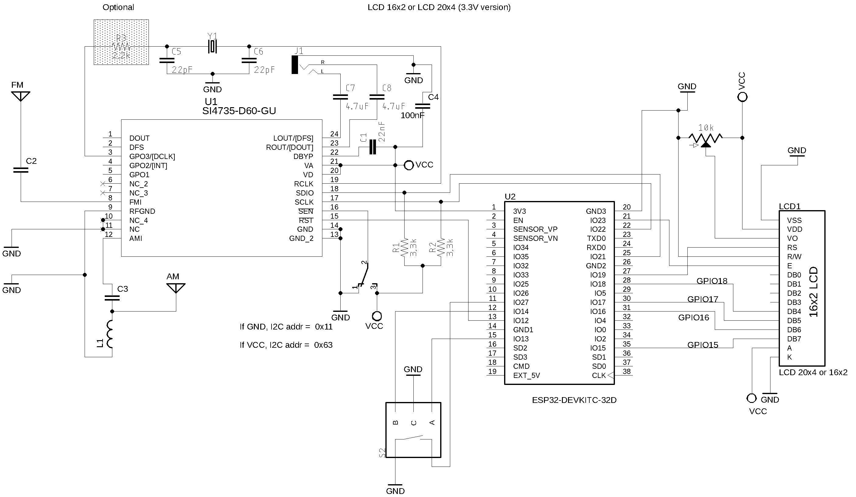
Wire up
ESP32 Wire up with LCD, encoder/pushbutton and SI4735-D60
| Device name | Device Pin / Description | ESP32 |
|---|---|---|
| LCD 16x2 or 20x4 | ||
| D4 | GPIO18 | |
| D5 | GPIO17 | |
| D6 | GPIO16 | |
| D7 | GPIO15 | |
| RS | GPIO19 | |
| E/ENA | GPIO23 | |
| RW & VSS & K (16) | GND | |
| A (15) & VDD | +Vcc | |
| VO (see 20K tripot connection) | ———— | |
| SS473X | ||
| RESET (pin 15) | GPIO12 | |
| SDIO (pin 18) | GPIO21 | |
| SCLK (pin 17) | GPIO22 | |
| (*1)SEN (pin 16) | +Vcc or GND | |
| Encoder | ||
| A | CPIO13 | |
| B | GPIO14 | |
| PUSH BUTTON (encoder) | GPIO27 |
ESP32 and SI4735-D60 Digital Audio setup (I2S)
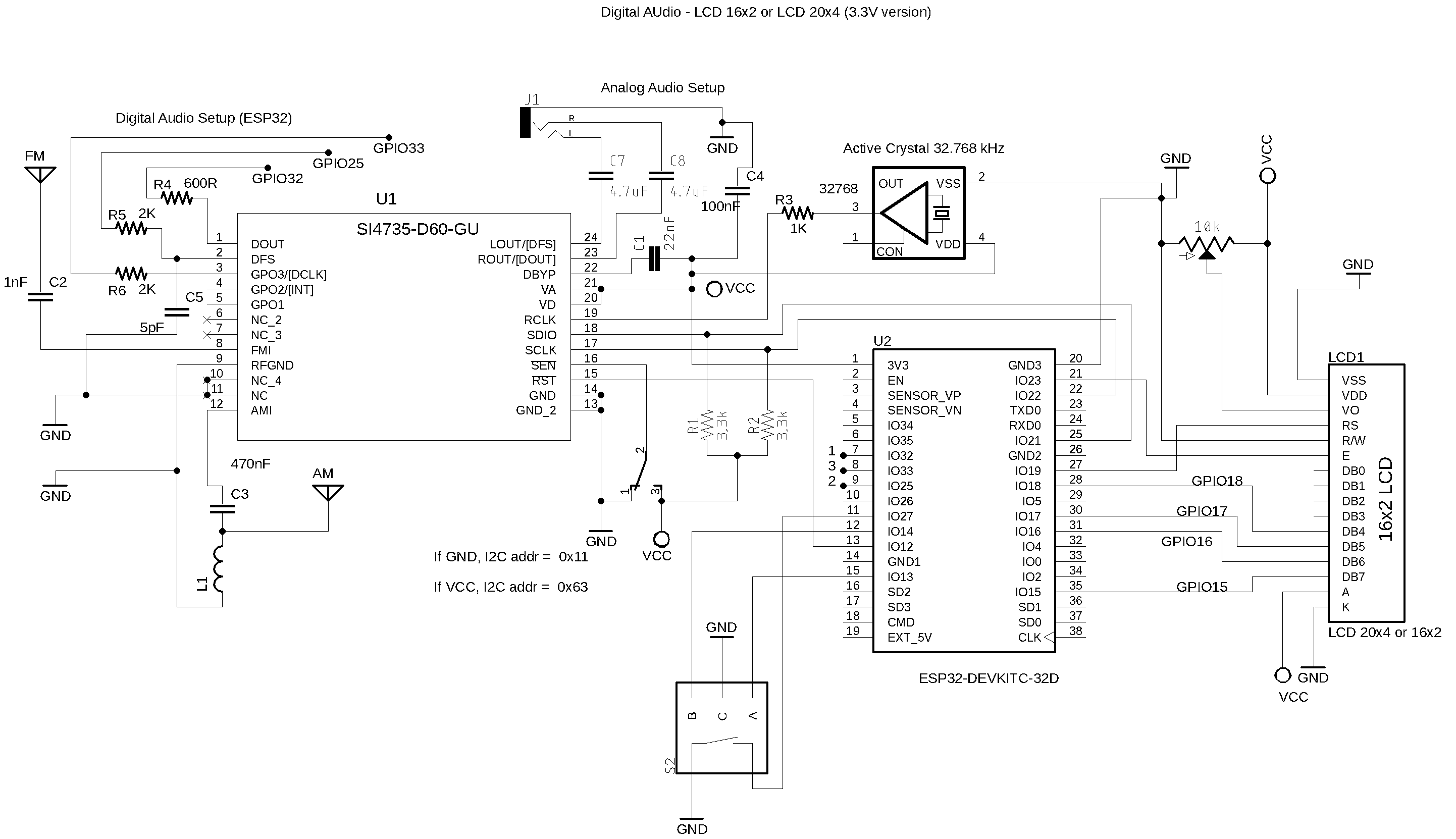
ESP32 Wire up with LCD, encoder/pushbutton and SI4735-D60
| Device name | Device Pin / Description | ESP32 |
|---|---|---|
| LCD 16x2 or 20x4 | ||
| D4 | GPIO18 | |
| D5 | GPIO17 | |
| D6 | GPIO16 | |
| D7 | GPIO15 | |
| RS | GPIO19 | |
| E/ENA | GPIO23 | |
| RW & VSS & K (16) | GND | |
| A (15) & VDD | +Vcc | |
| VO (see 20K tripot connection) | ———— | |
| SS473X | ||
| RESET (pin 15) | GPIO12 | |
| SDIO (pin 18) | GPIO21 | |
| SCLK (pin 17) | GPIO22 | |
| (*1)SEN (pin 16) | +Vcc or GND | |
| Encoder | ||
| A | CPIO13 | |
| B | GPIO14 | |
| PUSH BUTTON (encoder) | GPIO27 |
The table below shows the SI4735, DAC MAX98357A and ESP32 wireup
| Si4735 | Function | DAC MAX98357A | ESP32 |
|---|---|---|---|
| pin 1 | DOUT | DIN | SerialData / GPIO32 |
| pin 2 | DFS | RC | WordSelect / GPIO25 |
| pin 3 | DCLK | BCLK | ContinuousSerialClock / GPIO33 |
The table below shows the SI4735, DAC CJMCU and ESP32 wireup
| Si4735 | Function | DAC MAX98357A | ESP32 |
|---|---|---|---|
| pin 1 | DOUT | DIN | SerialData / GPIO32 |
| pin 2 | DFS | WSEL | WordSelect / GPIO25 |
| pin 3 | DCLK | BCLK | ContinuousSerialClock / GPIO33 |
Example SI47XX_03_ESP32_ALL_IN_ONE_TFT
Still under construction this sketch will show how to use TFT with ESP32, Si4735 device and Si4735 Arduino Library.
ESP32 and TFT wire up
| LCD SCREEN | NODEMCU ESP32 PIN |
|---|---|
| VCC | 3.3V |
| GND | GND |
| LED | 3.3V |
| SCL (SPI Clock) | GPIO18 / VSPI SCK (SPI Clock) |
| SDA (SPI Data) | GPIO23 / VSPI MOSI (MOSI, Data to Screen) |
| RS or DC | GPIO2 (In some boards it is labelled as DC) |
| RST (Screen reset) | GPIO4 |
| CS or SS | GPIO5 VSPI SS (Slave Select or Chip Select) |
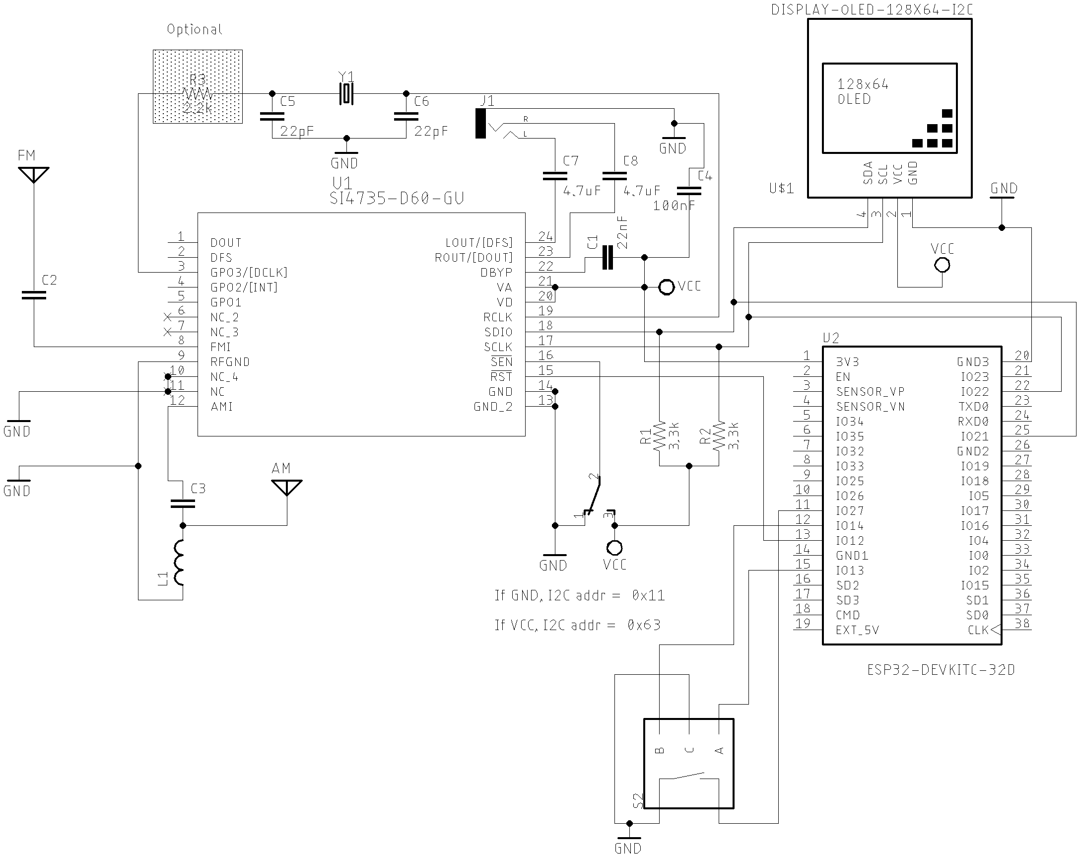
ESP32 OLED_IN_ONE sketch
Wire up
ESP32 and components wire up.
| Device name | Device Pin / Description | ESP32 |
|---|---|---|
| OLED | ||
| SDA/SDIO | GPI21 | |
| SCL/SCLK | GPI22 | |
| Encoder | ||
| A | GPIO 13 | |
| B | GPIO 14 | |
| PUSH BUTTON (encoder) | GPIO 27 |
ESP32 OLED_IN_ONE_TWO_ENCODERS sketch
Wire up
| Device name | Device Pin / Description | ESP32 |
|---|---|---|
| OLED | ||
| SDA/SDIO | GPI21 | |
| SCL/SCLK | GPI22 | |
| Encoder1 | ||
| A | GPIO 13 | |
| B | GPIO 14 | |
| PUSH BUTTON | GPIO 27 | |
| Encoder2 | A | GPIO 25 |
| B | GPIO 26 | |
| PUSH BUTTON (encoder) | GPIO 32 |