Examples
This folder has some examples that might help you to use the Si470X Arduino Library in your receiver project. If you find some error or problem during your implementation, please let me know.
This project is about a library to control the SI4701/02/03 devices and the focus of this project is the library and its functionalities. Please, don’t ask me to assist you in your: displays, encoders, buttons or something else out the library scope. Thanks.
The examples stored in this folder are made to assist you to build your own sketch. Therefore, it is important to say that there was no care with the layout. This part of the project stays with you.
The si470x_01_serial_monitor folder shows how you can check your circuit by using just the Arduino IDE Serial Monitor to control the receiver. Check the examples with Atmega328 and ESP32. In the sketch you will find the wireup with Atmega328 or ESP32 and si470x device.
The si470x_02_TFT_display folder has an example with the traditional Display TFT based on ST7735. In the sketch you will find the wireup with display and si470x device.
The si470x_03_STM32_OLED folder has an example with the traditional OLED I2C display and the breakout board SI3703. In the sketch you will find the wireup with display and si470x device.
Donate
TFT SCHEMATIC
The schematic below shows the receiver example with TFT display, encoder and push buttons.
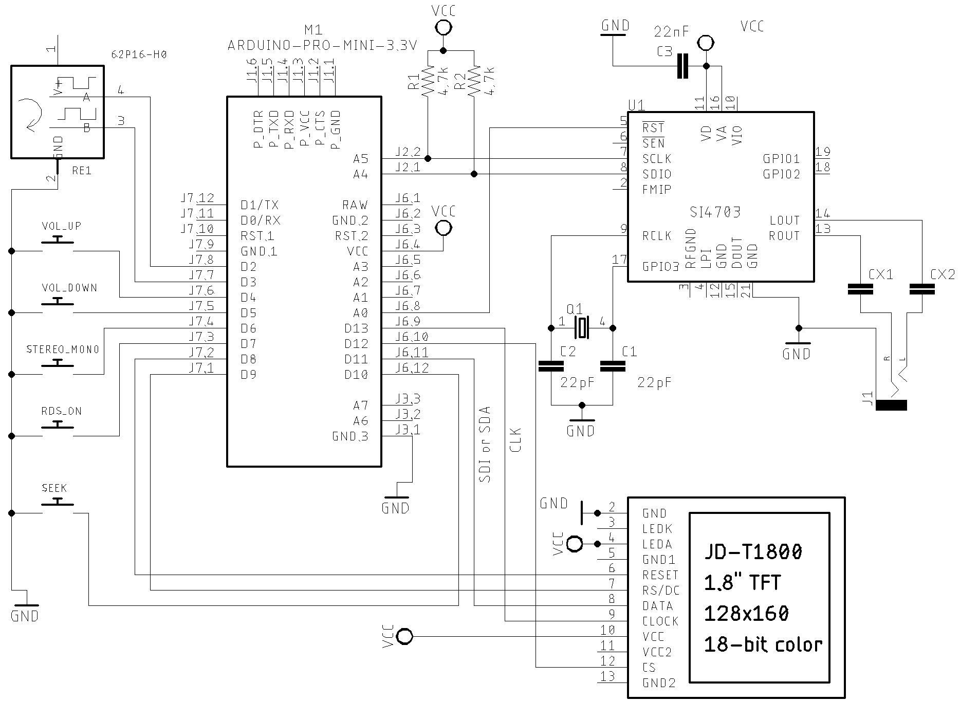
In general, the SI4703 device is already sold in kit or shield format. So, the circuit above can help you to connect the arduino to the shield. In this case, you will not need the crystal, pull up resistors and audio jack output. Also, the labels will guide you. The table bellow shows the connections.
Wire up on Arduino UNO, Pro mini or other based on ATmega 328.
| Device name | Device Pin / Description | Arduino Pin |
|---|---|---|
| Display TFT | ||
| RST (RESET) | 8 | |
| RS or DC | 9 | |
| CS or SS | 10 | |
| SDI or SDA or DATA | 11 | |
| CLK | 13 | |
| Si470X | ||
| RESET (pin 5) | 14 / A0 | |
| SDIO (pin 8) | A4 | |
| SCLK (pin 7) | A5 | |
| Buttons | ||
| Volume Up | 4 | |
| Volume Down | 5 | |
| Stereo/Mono | 6 | |
| RDS ON/off | 7 | |
| SEEK (encoder button) | 12 | |
| Encoder | ||
| A | 2 | |
| B | 3 |
ATtiny84 Schematic
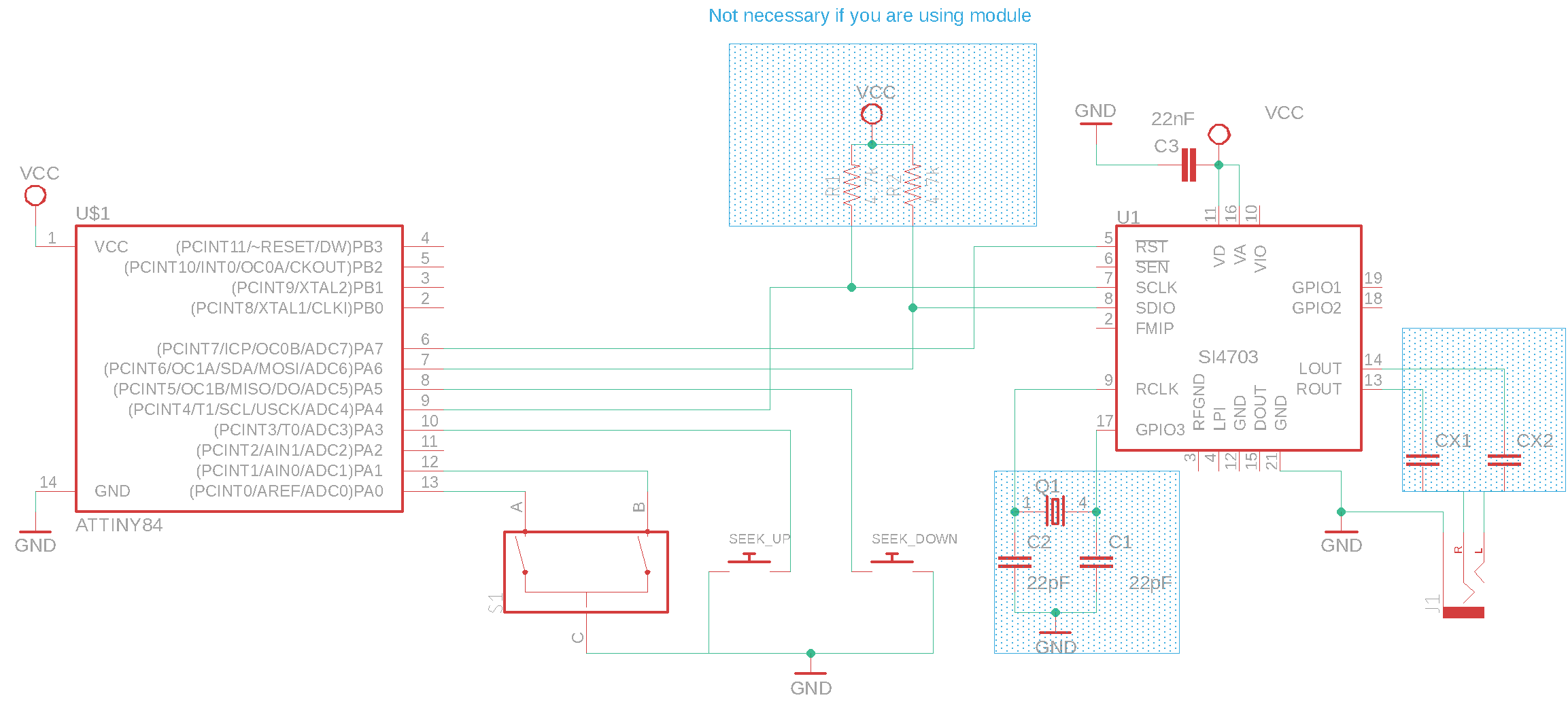
ATtiny84 and Si470X wireup
| Si470x pin | Attiny84 REF pin | Physical pin |
|---|---|---|
| RESET /RST | 7 | 6 |
| SEEK_UP | 3 | 10 |
| SEEK_DOWN | 5 | 8 |
| ENCODER_PIN_A | 0 | 13 |
| ENCODER_PIN_B | 1 | 12 |
| SDIO / SDA | SDA | 7 |
| SCLK / CLK | SCL | 9 |
Attiny85 Schematic
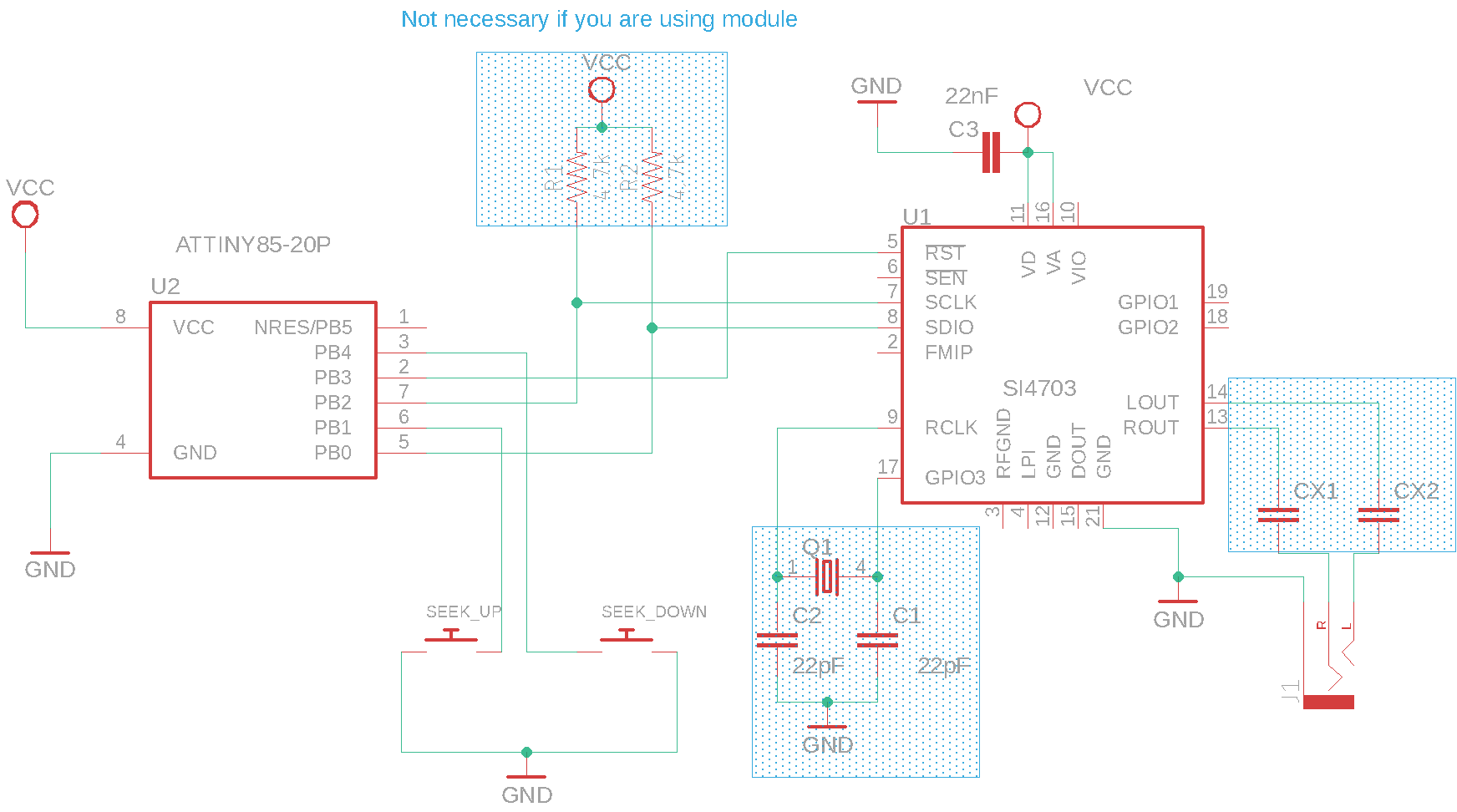
ATtiny85 and Si470X wireup
| Si470x pin | Attiny85 REF pin | Physical pin |
|---|---|---|
| RESET /RST | PB3 | 2 |
| SEEK_UP | PB1 | 6 |
| SEEK_DOWN | PB4 | 3 |
| SDIO / SDA | SDA | 5 |
| SCLK / CLK | SCL | 7 |