PU2CLR BK108X Arduino Library
The BK1088E is a single-chip solution for receiving AM, FM, and shortwave radio. Using inexpensive components (Arduino Pro Mini, some push buttons, and a standard OLED or TFT display), the hobbyists can build serviceable little receiver based on BK1088E with impressive performance.
This project involves a cross-platform Arduino Library designed to control the BK1086 and BK1088 devices. The BK108X Arduino Library is based on the documentation titled “BK1086/88E BROADCAST AM/FM/SW/LW RADIO RECEIVER; Rev.1.4” provided by BEKEN Corporation. Its purpose is to enable seamless control and integration of the BK1086 and BK1088 devices within Arduino projects.
This library can be freely distributed using the MIT Free Software model.
Copyright (c) 2020 Ricardo Lima Caratti.
Contact: pu2clr@gmail.com.
Donate
If you find this project useful, consider making a donation so that the author of this library can purchase components and modules for improvements and testing of this library. Click here to donate.
About Me
I hold a Master’s degree in Educational Technology from the Federal University of Ceará, where I delved into the ways technology can enhance learning experiences. My passion for computer science led me to specialize in it, focusing on Distributed Systems Development with an Object-Oriented approach, at the University of Brasília. My academic journey began with a Bachelor’s degree in Information Systems from the União Pioneira de Integração Social (UPIS-Brasília). Outside the classroom, my main hobbies are electronics and Amateur Radio.
Contents
- Preface
- BK1086/88E features
- Library Installation
- API Documentation
- Functional Block Diagram
- BK1086/88E TSSOP20 pinout
- Schematic
- Sketch examples
- Videos
- References
Preface
At the end of 2019, I embarked on several Arduino library development projects aimed at controlling DSP receivers. The initial endeavor involved creating an Arduino library for the SI4844, followed by libraries for the Si473X family, all manufactured by Silicon Labs. The positive reception and enthusiasm from radio listeners, experimenters, and hobbyists regarding the use of these libraries prompted me to expand my efforts.
As a result, I developed additional libraries for the AKC695X, KT0915, SI470X, and RDA5807, catering to the Arduino IDE platform. While researching the BK1086/88 Datasheet, I realized its suitability for radio enthusiasts and hobbyists. Initially, I found limited documentation available compared to the previously mentioned devices. This motivated me to gather as much information as possible about the BEKEN family of devices.
I reached out to BEKEN Corporation to request information about the BK1086/88E, and I am grateful for their prompt response and attention. I would like to extend my sincere appreciation to BEKEN Corporation for their cooperation and assistance in this endeavor.
This library is based on the BEKEN manual “BK1086/88 - BROADCAST AM/FM/SW/LW RADIO RECEIVER REV1.3” provided by BEKEN Corporation and experiments made by me during the development process.
If you are a hobbyist, a radio enthusiast and enjoy Arduino, this project is for you.
All Band receiver with BK1088E and LilyGo panel
All Band receiver with BK1088E and LilyGo panel
Presentation videos
BK1088E FM, AM (LW, MW and SW) DSP receiver working with Arduino
MIT License
Copyright (c) 2019 Ricardo Lima Caratti
Permission is hereby granted, free of charge, to any person obtaining a copy of this software and associated documentation files (the “Software”), to deal in the Software without restriction, including without limitation the rights to use, copy, modify, merge, publish, distribute, sublicense, and/or sell copies of the Software, and to permit persons to whom the Software is furnished to do so, subject to the following conditions:
The above copyright notice and this permission notice shall be included in all copies or substantial portions of the Software.
THE SOFTWARE IS PROVIDED “AS IS”, WITHOUT WARRANTY OF ANY KIND, EXPRESS OR IMPLIED, INCLUDING BUT NOT LIMITED TO THE WARRANTIES OF MERCHANTABILITY, FITNESS FOR A PARTICULAR PURPOSE AND NONINFRINGEMENT. IN NO EVENT SHALL THE AUTHORS OR COPYRIGHT HOLDERS BE LIABLE FOR ANY CLAIM, DAMAGES OR OTHER LIABILITY, WHETHER IN AN ACTION OF CONTRACT, TORT OR OTHERWISE, ARISING FROM, OUT OF OR IN CONNECTION WITH THE SOFTWARE OR THE USE OR OTHER DEALINGS IN THE SOFTWARE.
Thanks
Mr. Peng Roy, from BEKEN Corporation, for providing me with the technical information on the BK1086/88.
Your support is important
If you have suggestions to improve this project, please let me know.
BK1086/88 features
Main features
- Worldwide 64~108 MHz FM band support;
- Worldwide 520~1710kHz AM band support;
- LW band support(153-279kHz,BK1088E only)
- SW band support(2.3-21.85MHz, BK1088E only);
- Automatic gain control(AGC);
- Automatic frequency control(AFC);
- Digital FM stereo decoder;
- Automatic FM stereo/mono blend;
- Automatic noise suppression;
- 50us/75us de-emphasis;
- RDS/RBDS decoder;
- 2.4 ~ 5.5 V supply voltage;
- Wide range reference clock support;
- 32.768KHz crystal oscillator.
Useful information
- BK1086/88 can be controlled by an MCU through 2-wire I2C mode.
- The BK1088 already comes with 40K internal pull-up resistors on the i2c bus. Probably, no external pull-up resistors will be needed. However, depending on the size of the bus, consider using external pull-up resistors;
- BK1086/88 has an internal automatic tuning technology, which can automatically adjust the internal variable capacitance value to make the resonant circuit in the best resonance state at the current operating frequency, thus greatly simplifying the front-end design;
- BK1086 only supports FM and medium wave, BK1088 supports short wave and long wave in addition to FM and medium wave;
Library Installation
You can install this library on your Arduino environment using different methods.
Installing via Arduino IDE
This library is available on Arduino IDE platform. This video will show you how to install the Arduino Library for the BK1086 / 88 DSP device on your local computer.
Installing via the repository
With this approach, you will have the most current version of the library. However, it may not be the most stable version. This is because the current version is always in development. Prefer releases. Do you need some old version (release) of this library? If yes, check here.
To install the current version, you have to download this library in zip format. After, unzip the BK108X-master.zip file in your Arduino Library folder.
- On Windows: “My Documents\Arduino\libraries”
- On MAC OS: ˜/Documents/Arduino/libraries
- On Linux: ˜/Arduino/libraries
Functional Block Diagram
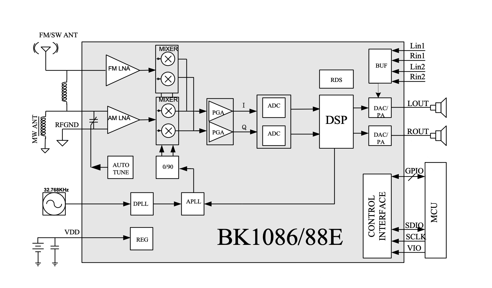
Source: “BK1086/88E BROADCAST AM/FM/SW/LW RADIO RECEIVER; Rev.1.3; page 3”
BK1086/88E TSSOP20 pinout
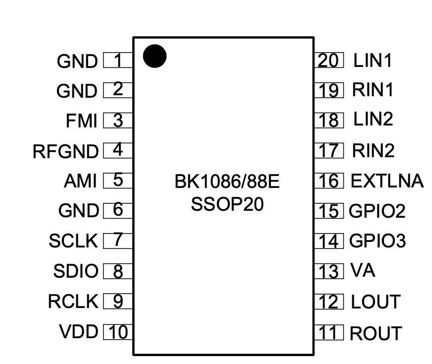
Source: “BK1086/88E BROADCAST AM/FM/SW/LW RADIO RECEIVER; Rev.1.3; page 23”
| Pin Number | Name | Description |
|---|---|---|
| 1 | GND | Ground. Connect to ground plane on PCB |
| 2 | GND | Ground. Connect to ground plane on PCB |
| 3 | FMI | FM RF input |
| 4 | RFGND | RF ground |
| 5 | AMI | MW/SW/LW RF input |
| 6 | GND | Ground. Connect to ground plane on PCB |
| 7 | SCLK | Clock for Serial communications |
| 8 | SDIO | Serial data input/output |
| 9 | RCLK | 32.768kHz - 38.4MHz external reference clock input/32.768KHz Oscillator input |
| 10 | VDD | Power supply for digital and I/O |
| 11 | ROUT | Right audio output |
| 12 | LOUT | Left audio output |
| 13 | VA | Power supply for analog |
| 14 | GPIO3 | General purpose output 3 |
| 15 | GPIO2 | General purpose output 2 |
| 16 | EXTLNA | External LNA control |
| 17 | RIN2 | Line in input (Right channel2) |
| 18 | LIN2 | Line in input (Left channel2) |
| 19 | RIN1 | Line in input (Right channel1) |
| 20 | LIN1 | Line in input (Left channel1) |
Schematic
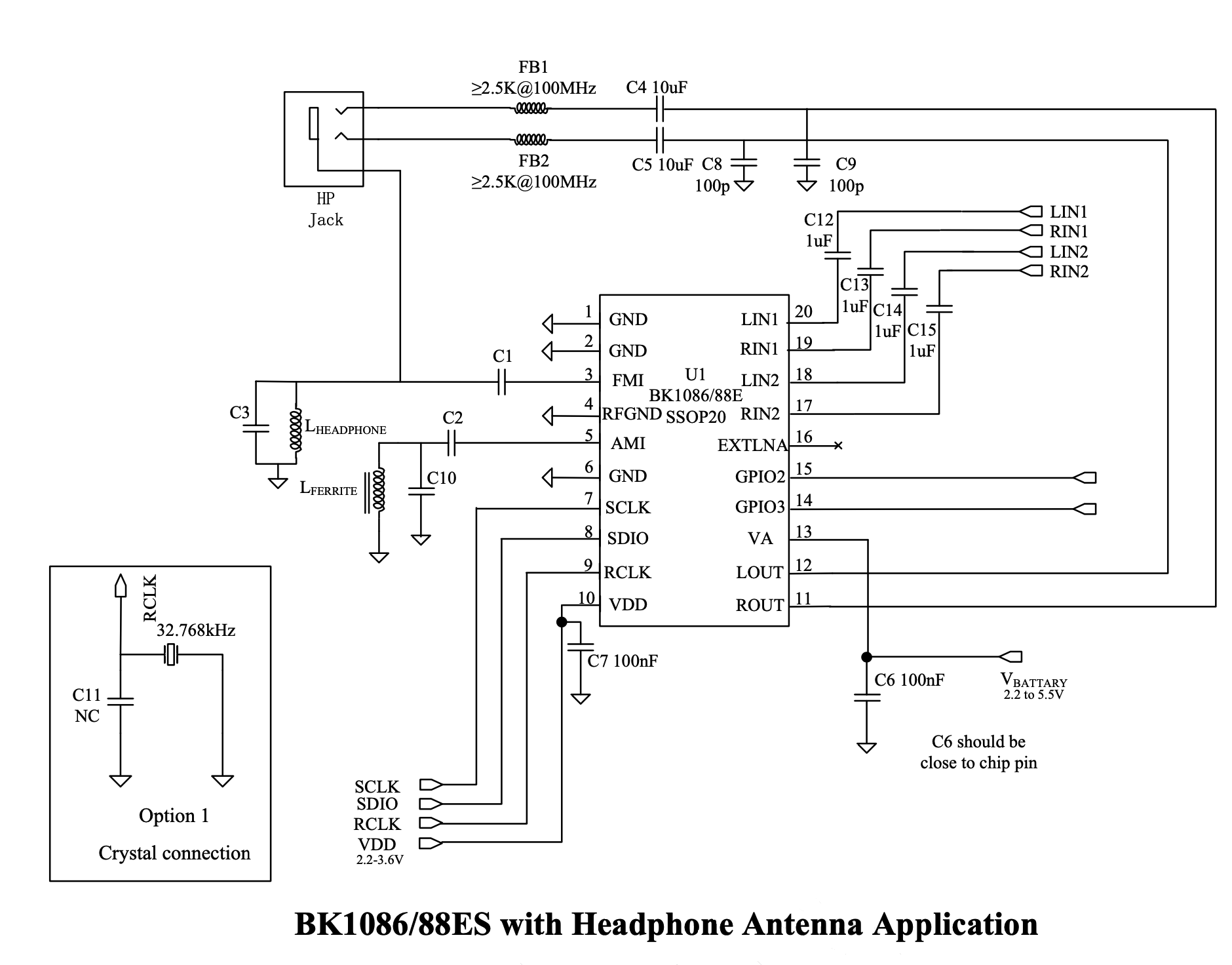
BEKEN Typical Application Schematic
The image below was extracted from “BK1086/88E BROADCAST AM/FM/SW/LW RADIO RECEIVER; Rev.1.3; page 25”. It is a basic circuit suggested by BEKEN.
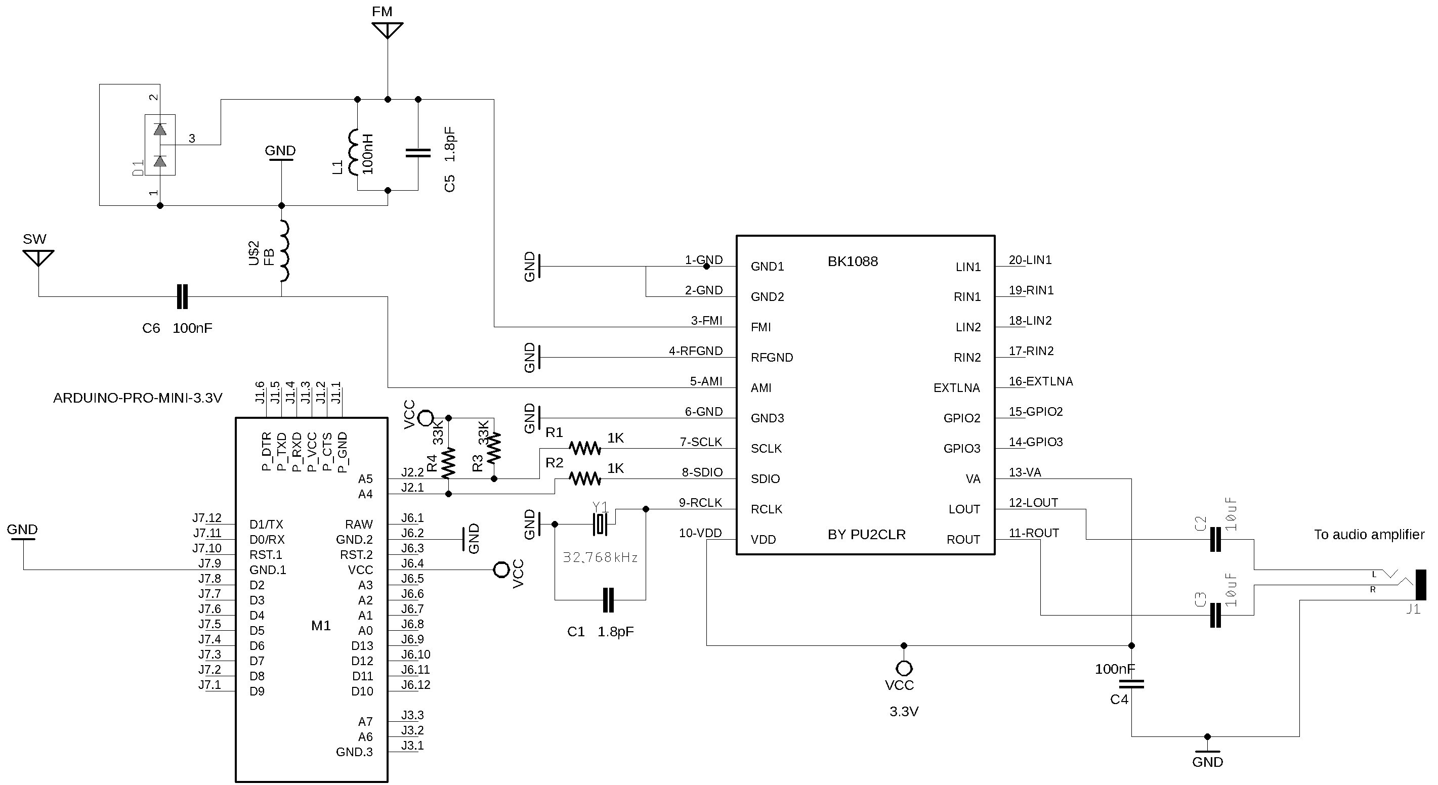
BK1088E(SSOP20) and Arduino Schematic
The schematic provided below is based on the typical application schematic provided by BEKEN and modified to work with the Arduino controller. The front-end circuit has been adjusted to utilize a regular antenna instead of a headphone antenna setup.
This circuit primarily serves the purpose of testing the BK108X Arduino Library. However, you may be pleasantly surprised by the performance of this simple circuit, thanks to the advanced features of the BK1086/88 device. It is important to note that while this receiver is not intended to meet the expectations of demanding listeners, it serves as a starting point. If desired, you can enhance its sensitivity, improve output sound quality, and add other desired features by incorporating additional devices into the circuit.
The example folder can guide you to check your circuit via Arduino sketches
Troubleshoot
- Place C1 (1.8pF) and the 32768KHz crystal as close as possible from the BK1088 pin 9;
- Place C4 (100nF) as close as possible from the BK1088 pin 13;
- Try to keep the length of the I2C bus as short as possible;
- If you check the circuit by running the POC_01_CIRCUIT_TEST.ino and get the Chip Id value -1 (0xFF):
- Check whether the DC voltage on pin 10 and 13 are correct;
- Be sure I2C connections are right;
- Be sure whether the I2C bus speed used by your MCU master (Arduino) is correct;
- If you are using a BK1088, the Chip Id value should be 4224 (0x1080)
- The frequency shown on display or Arduino IDE Serial Monitor is different from the real frequency.
- You might have problem with reference clock. If you are using the 32.768KHz crystal, check whether it is working;
- If you are using an external clock input, check the signal with an oscilloscope (check the RCLK);
- By default, this library used 32.768KHz as reference clock;
- If you need to use external reference clock or a crystal with different clock, please, read the [API documentation} (https://pu2clr.github.io/BK108X/extras/docs/html/index.html)
BK1088 and different reference clock frequency
I came across the following guide online regarding different reference clock frequencies: To accommodate the specific clock signal used, the internal registers should be configured as follows:
- Calculate the value using the formula (Freq/512)+0.5, resulting in an 18-bit hexadecimal number.
- Set Bit[17:16] of REG28 to the corresponding values and set Bit[15:0] of REG29 to the reverse order of the lower 16 bits of the calculated binary number.
- Please, note that the bit order of REG29 should be opposite to the calculation result. Bit[15] corresponds to REG29[0], and Bit[0] corresponds to REG29[15].
- For example, if the frequency is 12MHz: Calculate (12000000/512) + 0.5 = 23438. Convert it to hexadecimal: 0x5B8E. Convert the lower 16 bits to binary and reverse the order: 0111 0001 1101 1010. Convert it back to hexadecimal: 0x71DA. Hence, the configuration for the 12MHz clock would be: REG28 remains unchanged at 0x0000, and REG29 changes from 0x0200 to 0x71DA.
This implementation is found within the powerUp function of this library (refer to void BK108X::powerUp() in the BK108X.cpp file). However, it did not yield successful results in my tests. Currently, this library solely supports the 32.768kHz passive crystal oscillator. If you possess any knowledge on how to implement it differently, please inform me.
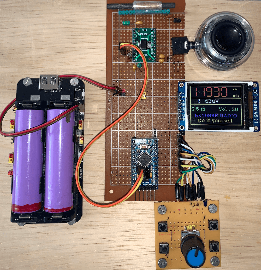
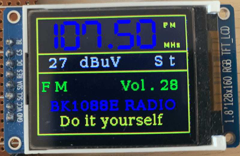
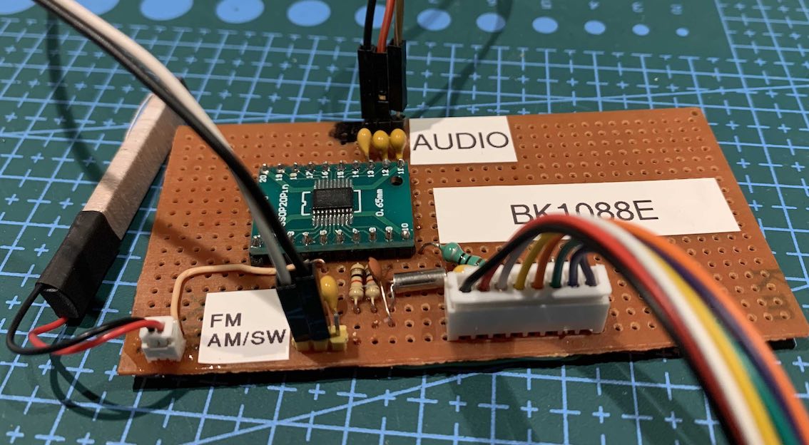
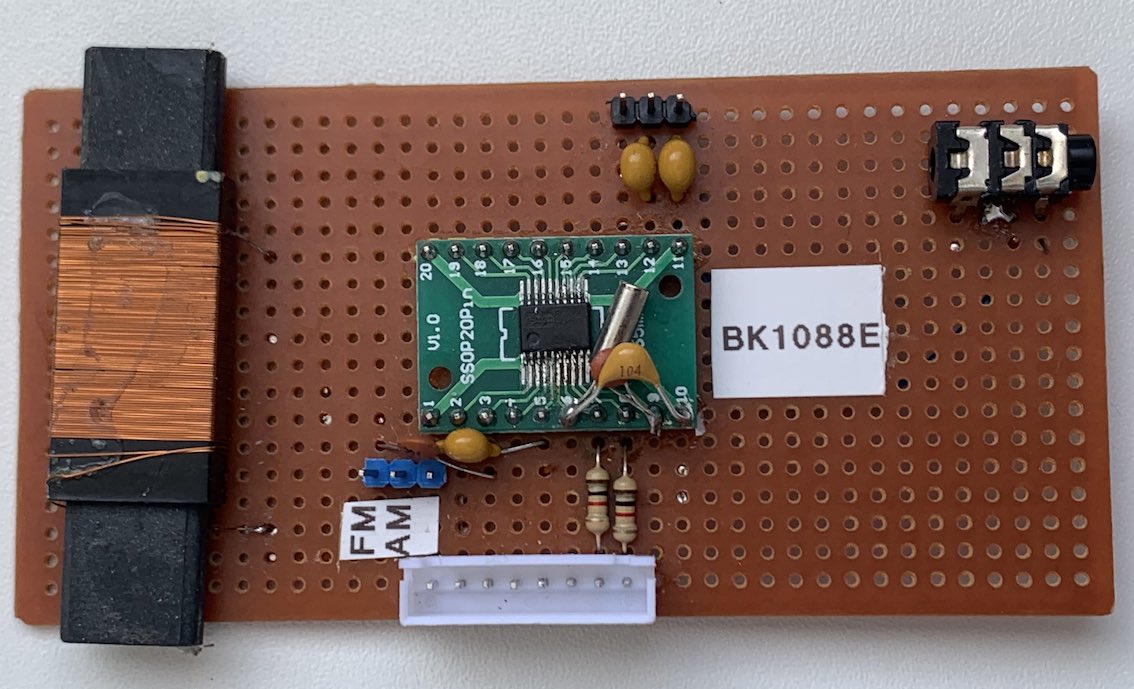
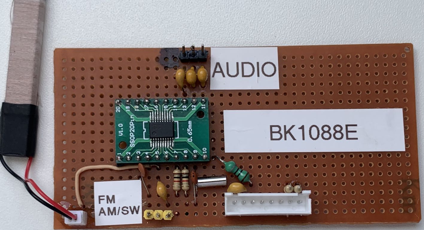
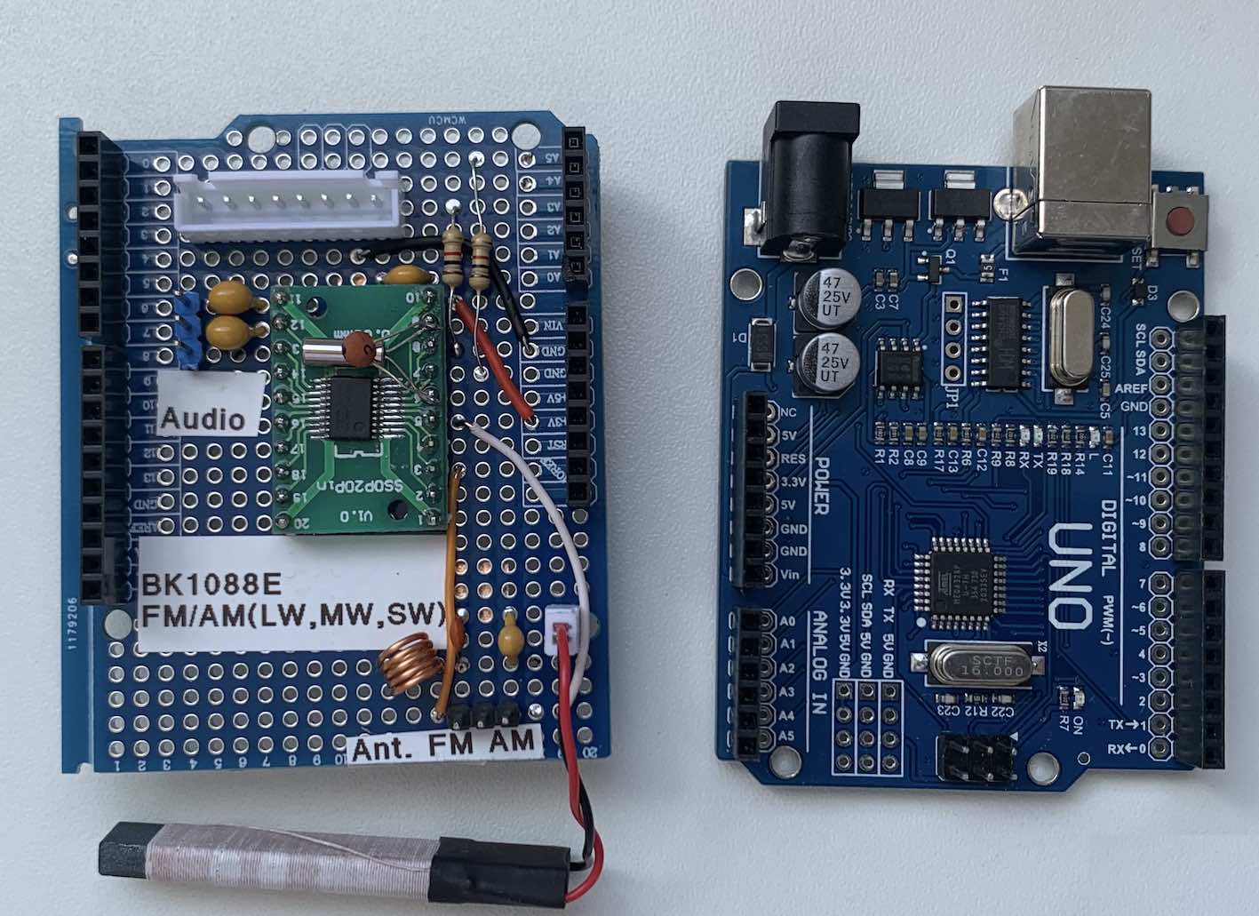
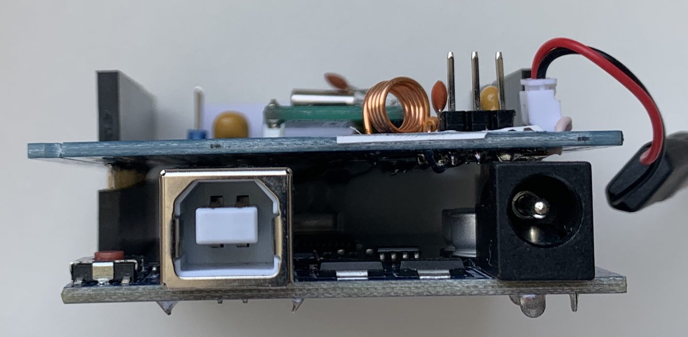
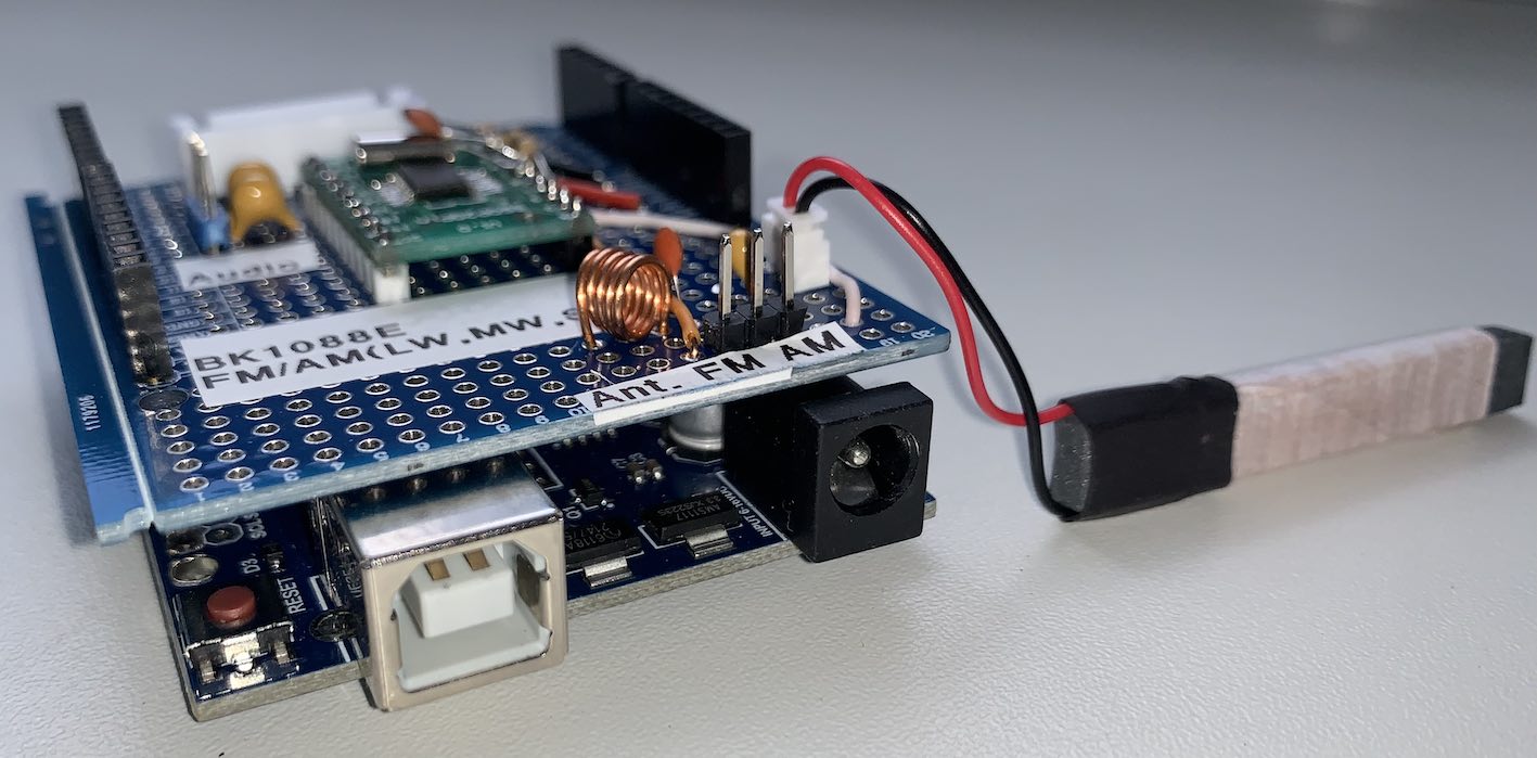
Photos
The following prototypes are based on the electrical schematics available in this repository and aim to guide experimenters in assembling a receiver based on the BK1088E device.
In some prototypes, the receiving module is separated from the controller module. This aids in conducting tests with various different configurations. Additionally, it helps mitigate noise emitted by the controller. See the videos posted on youtube.
Prototype: Photo 1
Prototype: Photo 2
Prototype: Photo 3
Prototype: Photo 4
Prototype: Photo 5
Arduino UNO SHIELD
The following prototype is highly beneficial for Arduino UNO users looking to develop a receiver utilizing the BK1088E. Additionally, this model offers the flexibility to incorporate a wide range of display options.
Videos
- All Band receiver with BK1088E and PU2CLR BK108X Arduino Library
- All Band Receiver with BK1088E Arduino Library and LilyGO T Embed
- AM / FM-RDS Receiver with PU2CLR BK108X Arduino Library, Nano and Nokia 5110
- FM/RDS Radio with BK1088E - ESP32 - LCD16x02 with PU2CLR BK108X Arduino Library
- BK1088E FM, AM (LW, MW and SW) DSP receiver working with Arduino
- DSP BK1088E AM/MW and FM test with PU2CLR BK108X Arduino Library
- DSP BK1088E SW test with PU2CLR BK108X Arduino Library
See also
- PU2CLR Si4735 Library for Arduino. This library was built based on “Si47XX PROGRAMMING GUIDE; AN332” and it has support to FM, AM and SSB modes (LW, MW and SW). It also can be used on all members of the SI47XX family respecting, of course, the features available for each IC version;
- PU2CLR SI4844 Arduino Library. This is an Arduino library for the SI4844, BROADCAST ANALOG TUNING DIGITAL DISPLAY AM/FM/SW RADIO RECEIVER, IC from Silicon Labs. It is available on Arduino IDE. This library is intended to provide an easier interface for controlling the SI4844.
- PU2CLR AKC695X Arduino Library. The AKC695X is a family of IC DSP receiver from AKC technology. The AKC6955 and AKC6959sx support AM and FM modes. On AM mode the AKC6955 and AKC6959sx work on LW, MW and SW. On FM mode they work from 64MHz to 222MHz.
- PU2CLR KT0915 Arduino Library. The KT0915 is a full band AM (LW, MW and SW) and FM DSP receiver that can provide you a easy way to build a high quality radio with low cost.
- PU2CLR RDA5807 Arduino Library. The RDA5807 is a FM DSP integrated circuit receiver (50 to 115MHz) with low noise amplifier support. This device requires very few external components if compared with other similar devices. It also supports RDS/RBDS functionalities, direct auto gain control (AGC) and real time adaptive noise cancellation function.
- PU2CLR SI470X Arduino Library. It is a Silicon Labs device family that integrates the complete functionalities for FM receivers, including RDS (Si4703).
References
- BK1086/88E - BROADCAST AM/FM/SW/LW RADIO RECEIVER; Rev 1.3 (Copyright©2012 by Beken Corporation);
- BK1086/88 Application Manual (In Chinese - Copyright©2012 by Beken Corporation);
- BK1088ES
- 1201682 Radio Alarm Clock with Bluetooth Speaker / Bluetooth Alarm Clock Radio Schematics Circuit Diagram Shenzhen Great Power Enterprise;
- AudioComm RAD-F630Z
- Tutorial: Arduino and the I2C bus – Part One
- GNL Project