PU2CLR AKC695X Arduino Library
This library facilitates control over the AKC6955 / M6955 DSP radio devices using Arduino.
The development was primarily based on the AKC6955 stereo FM / TV / MW / SW / LW digital tuning radio documentation provided by AKC technology. Additionally, various other sources assisted the author in crafting this library. More information about these can be found in the References section.
Intended to be compatible with all AKC695X family members featuring an I²C bus interface, this library accommodates the unique features inherent to each IC variant. It’s imperative to review the device’s datasheet before initiating your project.
Furthermore, distribution of this library is permitted under the MIT Free Software license.
Copyright (c) 2020 Ricardo Lima Caratti.
Contact: pu2clr@gmail.com.
Donate
If you find this project useful, consider making a donation so that the author of this library can purchase components and modules for improvements and testing of this library. Click here to donate.
About Me
I hold a Master’s degree in Educational Technology from the Federal University of Ceará, where I delved into the ways technology can enhance learning experiences. My passion for computer science led me to specialize in it, focusing on Distributed Systems Development with an Object-Oriented approach, at the University of Brasília. My academic journey began with a Bachelor’s degree in Information Systems from the União Pioneira de Integração Social (UPIS-Brasília). Outside the classroom, my main hobbies are electronics and Amateur Radio.
Facebook group
Be a member of Facebook group DSP receivers for hobbyists
Contents
- Preface
- Your support is important
- Library Features
- MIT License
- Library Installation
- About AKC695X / M695X DSP radio
- SCHEMATIC
- API Documentation
- Source code - Arduino sketch examples
- Videos
- References
- Commercial receivers based on AKC6955
Preface
AKC695X device family offer versatile FM/MW/SW/LW receiver solution by reducing the external components usually found in regular receivers. This device family will surprise hobbyists and experimenters with its simplicity to build FM and AM (LW, MW, SW) receivers.
There are currently some receivers based on DSP technology. The KT0915 and SI4735 devices are some examples widely disseminated in the market. This library was developed with the purpose of expanding the alternatives to hobbyists and radio listeners.
In this document you will see Arduino source codes, schematics, examples and tips to help you to build a receiver based on Arduino board and AKC695X devices. The project and examples shown here do not intend to be a real receiver for exigent listener. However, it is possible to start with it and after add some improvements. On the other hand, with the simple circuits shown here, the experimenter may be surprised with the AKC695X performance.
Presentation video
AKC6955 controlled by a standalone ATmega328 and LCD16x2
See also
- PU2CLR Si4735 Library for Arduino. This library was built based on “Si47XX PROGRAMMING GUIDE; AN332” and it has support to FM, AM and SSB modes (LW, MW and SW). It also can be used on all members of the SI47XX family respecting, of course, the features available for each IC version;
- PU2CLR SI4844 Arduino Library. This is an Arduino library for the SI4844, BROADCAST ANALOG TUNING DIGITAL * DISPLAY AM/FM/SW RADIO RECEIVER, IC from Silicon Labs. It is available on Arduino IDE. This library is intended to provide an easier interface for controlling the SI4844.
- PU2CLR AKC695X Arduino Library. The AKC695X is a family of IC DSP receiver from AKC technology. The AKC6955 and AKC6959sx support AM and FM modes. On AM mode the AKC6955 and AKC6959sx work on LW, MW and SW. On FM mode they work from 64MHz to 222MHz.
- PU2CLR KT0915 Arduino Library. The KT0915 is a full band AM (LW, MW and SW) and FM DSP receiver that can provide you a easy way to build a high quality radio with low cost.
- PU2CLR BK108X. The BK1086 and BK1088 are DSP receivers from BAKEN. The BK1088 is a BROADCAST FM and AM (LW, MW and ) RECEIVER and BK1086 is a subset of the BK1088 (it does not have LW and SW acording to the Datasheet).
- PU2CLR RDA5807 Arduino Library. The RDA5807 is a FM DSP integrated circuit receiver (50 to 115MHz) with low noise amplifier support. This device requires very few external components if compared with other similar devices. It also supports RDS/RBDS functionalities, direct auto gain control (AGC) and real time adaptive noise cancellation function.
- PU2CLR SI470X Arduino Library. It is a Silicon Labs device family that integrates the complete functionalities for FM receivers, including RDS (Si4703).
- PU2CLR MCP23008. It is an Arduino Library to control the MCP23008/MCP23S08 8-Bit I/O Expander. The MCP23008 device provides 8-bit, general purpose, parallel I/O expansion. It can be controlled via I2C bus applications. It is a great and inexpensive device that allow you to add more devices to be controlled by your Arduino board via I2C protocol.
- PU2CLR - PCF8574 Arduino Library. It is an Arduino Library to control the PCF8574 8-Bit I/O Expander. The PCF8574 device provides 8-bit, general purpose, parallel I/O expansion. It can be controlled via I²C bus applications. It is a great and inexpensive device that allow you to add more peripherals to be controlled by your Arduino board via I²C protocol.
- QN8066 FM DSP RX/TX Arduino Library. An easy-to-use interface for controlling the QN8066 FM transceiver and receiver.
More Arduino Projects developed by author
- Multipurpose signal generator with SI5351. It is a multipurpose signal generator controlled by Arduino. This project uses the SI5351 from Silicon Labs. The Arduino sketch is configured to control the SI5351 with three channels from 32.768kHz to 160MHz and steps from 1Hz to 1MHz.
- Shortwave Arduino Transmitter. This project is about a shortwave transmitter from 3 MHz to 30 MHz. It uses the SI5351 oscillator from Silicon Labs controlled by Arduino. Also, you can use it with a crystal oscillator. In this case, you will not need the SI5351 device and Arduino.
- Android and iOS Bluetooth Remote Control for PU2CLR Arduino Library DSP receivers. This project is an extension of the Arduino library projects for: SI4735; AKC6959 and KT0915. It is a simple example that shows a way to use your smartphone as a remote control via Bluetooth. In order to follow the steps presented here, I am assuming that you have some knowledge in development for mobile devices. Also, you will need to be familiar with the Javascript programming language. The development environment used by this project is the Apache Cordova. Cordova is a open-source mobile development framework that allows you to develop cross-platform applications. That means you can code once and deploy the application in many system, including iOS and Android. Cordova provides an easy way to develop for iOS and Android.
- Band Pass Filter controlled by Arduino. It is a HF band pass filter controlled by Arduino. It is designed for HF receivers. With this project, you can use a set of up to four HF bandpass filters that can be selected by Arduino. To do that you will need just two digital Arduino pins.
Your support is important
If you would like to support this library development, consider joining this project via Github. Alternatively, make suggestions on new features and report errors if you find them. Thank you!
Library Features
This library uses the I²C communication protocol and implements most of the functions offered by the AKC695X (BROADCAST AM / FM / SW / LW RADIO RECEIVER).
The main features of this library are listed below.
- Open Source. It is free. You can use, copy, modify, merge, publish, distribute, sublicense, and/or sell copies of the Software. See MIT License to know more;
- Built based on AKC6955 stereo FM / TV / MW / SW / LW digital tuning radio;
- C++ Language and Object-oriented programming. You can easily extend the AKC695X class by adding more functionalities;
- Available on Arduino IDE (via Manage Libraries). Easy to install and use;
- Cross-platform. You can compile and run this library on most of board available on Arduino IDE (Examples: ATtiny85, boards based on ATmega328 and ATmega-32u4, ATmega2560, ARM Cortex, STM32, Arduino DUE, ESP32 and more);
- Simplifies projects based on AKC695X IC family with support to I²C;
- Seeking function support;
- Support to 32.768kHz and 12MHz crystal oscillators;
- Support to audio controlled by the MCU (Arduino) or potentiometer;
- Real tim FM stereo or mono indicator;
- FM stereo or mono selecting;
- Real time signal level reading;
- Real time AM and FM carrier to noise ratio information (dB).
- Bandwidth selection for FM;
- Custom band support;
- More than 40 functions implemented.
MIT License
Copyright (c) 2019 Ricardo Lima Caratti
Permission is hereby granted, free of charge, to any person obtaining a copy of this software and associated documentation files (the “Software”), to deal in the Software without restriction, including without limitation the rights to use, copy, modify, merge, publish, distribute, sublicense, and/or sell copies of the Software, and to permit persons to whom the Software is furnished to do so, subject to the following conditions:
The above copyright notice and this permission notice shall be included in all copies or substantial portions of the Software.
THE SOFTWARE IS PROVIDED “AS IS”, WITHOUT WARRANTY OF ANY KIND, EXPRESS OR IMPLIED, INCLUDING BUT NOT LIMITED TO THE ARRANTIES OF MERCHANTABILITY, FITNESS FOR A PARTICULAR PURPOSE AND NONINFRINGEMENT. IN NO EVENT SHALL THE AUTHORS OR COPYRIGHT HOLDERS BE LIABLE FOR ANY CLAIM, DAMAGES OR OTHER LIABILITY, WHETHER IN AN ACTION OF CONTRACT, TORT OR OTHERWISE, ARISING FROM, OUT OF OR IN CONNECTION WITH THE SOFTWARE OR THE USE OR OTHER DEALINGS IN THE SOFTWARE.
Thanks
- Mr. FUJIURA Toyonori for some bug fixes.
Library Installation
You can install this library on your Arduino environment using different methods.
Installing via Arduino IDE
The video below shows how to install the PU2CLR AKC695X Arduino Library from your Arduino IDE.
PU2CLR AKC695X Arduino Library Installation
Installing via the repository
With this approach, you will have the most current version of the library. However, it may not be the most stable version. This is because the current version is always in development. Prefer releases. Do you need some old version (release) of this library? If yes, check here.
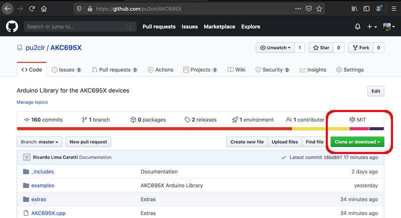
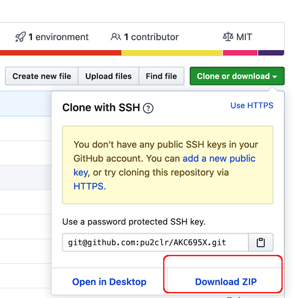
First, you have to download this library in zip format. The figures below show that.
Downloading from AKC695X PU2CLR Arduino Library repository
First step
Last step
After download, unzip the AKC695X-master.zip file in your Arduino Library folder. Check this folder path below.
- On Windows: “My Documents\Arduino\libraries”
- On MAC OS: ˜/Documents/Arduino/libraries
- On Linux: ˜/Documents/Arduino/libraries
About AKC695X / M695X DSP radio
The AKC695X is a family of IC DSP receiver from AKC technology. The AKC6955 and AKC6959sx support AM and FM modes. On AM mode the AKC6955 and AKC6969 work on LW, MW and SW. On FM mode they work from 64MHz to 222MHz.
AKC695X features
The table below shows some AKC695X devices family features.
| Feature | AKC6951 | AKC6955 | AKC6959sx |
|---|---|---|---|
| stand by 30 ~ 230MHz Any frequency FM demodulation | X | X | X |
| stand by 0.15 ~ 30MHz Any frequency AM demodulation | X | X | X |
| Preset FM band ( 64 ~ 108 MHz ) | X | X | X |
| stand by TV1 audio( 56.25 ~ 91.75 MHz ) | X | X | X |
| stand by TV2 audio( 174.75 ~ 222.25 MHz ) | X | X | X |
| Presets wave band ( 520 ~ 1730 kHz ) | X | X | X |
| Preset shortwave band ( 3.2 ~ 21.9 MHz ) | X | X | |
| Preset long-wave band ( 150 ~ 285 kHz ) | X | X | X |
| Custom support band | X | X | |
| It supports a wide supply voltage range: 2.0V ~ 4.5V | X | X | X |
| stand by 32.768kHz & 12MHz Passive mode crystal reference clock and Pin | X | X | X |
| Integrated audio amplifier (maximum power differential 0.5W ) | X | X | X |
| Two kinds of control volume: volume potentiometer and the volume register | X | X | X |
| Two kinds of de-emphasis modes: 50us / 75us | X | X | X |
| Support tuning lamp function | X | X | X |
| The audio output may be in phase, may be inverted output | X | X | X |
| Support for stereo line input | X | X | X |
| Support low-power standby mode, 3V When power consumption 10uA | X | X | X |
| Internal integrated PLL | X | X | X |
| Intelligent frequency control | X | X | X |
| AGC | X | X | X |
| Precise digital demodulation | X | X | X |
| Smart mute function | X | X | X |
| SW Increased tracking filter, greatly improving SW Audibility | X | X | |
| MW Precise tuning adaptive front end | X | X | X |
| FM Subwoofer | X | X | X |
| integrated LDO | X | X | X |
| According to the battery voltage, automatically adjust the volume | X | X | X |
| Pb-free / RoHS complian | X | X | X |
Sources: AKC6951, AKC6955 and AKC6959sx Datasheets.
ATTENTION: The AKC6952 and AKC6959 do not have I²C interface. So, they will not work with this library. Try AKC6951, AKC6955 or AKC6959sx.
Registers setup
This library uses the I²C protocols to read and write AKC695X registers. In this context, registers are memory position into the device.
The first 13 registers, you can use to change the behavior of the device. They are read and write registers. The registers from 20 to 27, can be used to get the current device status. They are read only registers.
By writing and reading these register, you can control the AKC695X devices.
Register operations
By using the registers 0 to 13, you can change the band, set the frequency, set the channel space, set the audio behavior and volume, set a custom band and more. The file AKC695X.h has details about the all registers used in the library. Also, you can read the API Documentation to know more about AKC695X registers.
There is no information about the register 10 and the registers 14 to 19 in the documentation used to develop this library.
To represent the information stored in the AKC695X registers, this library used the resources of the C / C ++ language: union, struct and typedef. This way, the user of this library will be able to customize it easily.
This approach is shown below for the registers 0, 1, 2 and 3.
Table Reg0
Reg0: configure register 0 (default: 0x4c) Address - Type 0x00 (RW)
| BIT | Label | Default | Function Description |
|---|---|---|---|
| 7 | power_on | 0 | 1 = On; 0 = Off |
| 6 | fm_en | 1 | 1 = FM; 0 = AM |
| 5 | tune | 0 | 1 = Trigger tune process. The STC bit is set high when the tune operation completes |
| 4 | seek | 0 | 1 = Trigger tune process. The STC bit is set high when the tune operation completes |
| 3 | seekup | 1 | 1 = Seek up; 0 = Seek down |
| 2 | mute | 1 | 0 = Normal operation; 1 = Mute L / R |
| 1:0 | rsv | 00 | Debug use, do not change this value using |
Source: AKC6955 stereo FM / TV / MW / SW / LW digital tuning radio
Be aware that the table above presents the data in order of the most significant bits to the least significant bits. In C/C++ representation of that data will be inverted. See the C/C++ code below.
Data representation in C/C++ for the register 0
typedef union {
    struct
    {
        uint8_t rsv : 2;      //!< Reserved - Debug use, do not change this value using
        uint8_t mute : 1;     //!< 1 - Mute L / R channel 0 - Normal operation
        uint8_t seekup : 1;   //!< Seek direction control bit. 0 = Seek down;  1 = Seek up
        uint8_t seek : 1;     //!< 0-> 1 Trigger tune process The STC bit is set high when the tune operation completes.
        uint8_t tune : 1;     //!< 0-> 1 Trigger tune process The STC bit is set high when the tune operation completes.
        uint8_t fm_en : 1;    //!< 1 = FM mode;  0 = AM mode
        uint8_t power_on : 1; //!< 1 = Chip on; 0 = Chip off
    } refined;
    uint8_t raw;
} akc595x_reg0;
It is important to say that the code above does not necessarily generate extra machine code. Much more than that, the code above guides the compiler on how to operate with the AKC695X bits stored into its registers. In this case register 0. If you have some experience in C/C++, you will know when you can use this approach instead direct bit manipulation and vice-versa.
The code below is an example of how this data structure can be used.
void AKC695X::powerOn(uint8_t fm_en, uint8_t tune, uint8_t mute, uint8_t seek, uint8_t seekup)
{
    akc595x_reg0 reg0;

    reg0.refined.power_on = 1;
    reg0.refined.rsv = 0;
    reg0.refined.fm_en = fm_en;
    reg0.refined.mute = mute;
    reg0.refined.seek = seek;
    reg0.refined.seekup = seekup;
    reg0.refined.tune = tune;

    setRegister(REG00, reg0.raw);

}
Table Reg1
Reg1: configure register 1 (default: 0x10) Address - Type 0x01 (RW)
| BIT | Label | Default | Function Description |
|---|---|---|---|
| 7:3 | amband | 0x2 | see table Table Reg1 amband |
| 2:0 | fmband | 0x00 | see table Table Reg1 fmband |
Source: AKC6955 stereo FM / TV / MW / SW / LW digital tuning radio
Data representation in C/C++ for the register 1
typedef union {
    struct
    {
        uint8_t fmband : 3; //!<
        uint8_t amband : 4; //!<
    } refined;
    uint8_t raw;
} akc595x_reg1;
The code below is an example of how the akc595x_reg1 can be used.
      .
      .
    akc595x_reg1 reg1;
      .
      .
    reg1.raw = 0;
    reg1.refined.fmband =  fm_band; // Selects the band will be used for FM (see fm band table)
    setRegister(REG01, reg1.raw);
      .
      .
Table Reg1 amband
The table below can help you to select the right band and its frequency limits. You might need to use it in your Arduino sketch.
| amband value | N# | Description |
|---|---|---|
| 00000 | 0 | LW, 0.15 ~ 0.285, 3K station search |
| 00001 | 1 | MW1, 0.52 ~ 1.71, 5K station search |
| 00010 | 2 | MW2, 0.522 ~ 1.62, 9K station search |
| 00011 | 3 | MW3, 0.52 ~ 1.71, 10K station search |
| 00100 | 4 | SW1, 4.7 ~ 10, 5K station search |
| 00101 | 5 | SW2, 3.2 ~ 4.1, 5K station search |
| 00110 | 6 | SW3, 4.7 ~ 5.6, 5K station search |
| 00111 | 7 | SW4, 5.7 ~ 6.4, 5K station search |
| 01000 | 8 | SW5, 6.8 ~ 7.6, 5K station search |
| 01001 | 9 | SW6, 9.2 ~ 10, 5K station search |
| 01010 | 10 | SW7, 11.4 ~ 12.2, 5K station search |
| 01011 | 11 | SW8, 13.5 ~ 14.3 |
| 01100 | 12 | SW9, 15 ~ 15.9 |
| 01101 | 13 | SW10, 17.4 ~ 17.9 |
| 01110 | 14 | SW11, 18.9 ~ 19.7, 5K station search |
| 01111 | 15 | SW12, 21.4 ~ 21.9, 5K station search |
| 10000 | 16 | SW13, 11.4 ~ 17.9, 5K station search |
| 10010 | 17 | MW4, 0.52 to 1.73, 5K station search |
| Other | 18+ | custom band, station search interval = 3K |
Table Reg1 fmband
| fmband value | N# | Description |
|---|---|---|
| 000 | 0 | FM1,87 ~ 108, station search space specified intervals |
| 001 | 1 | FM2,76 ~ 108, station search space specified intervals |
| 010 | 2 | FM3,70 ~ 93, with a space station search interval set |
| 011 | 3 | FM4,76 ~ 90, Tuning predetermined space intervals |
| 100 | 4 | FM5,64 ~ 88, with a space station search interval set |
| 101 | 5 | TV1,56.25 ~ 91.75, station search space specified intervals |
| 110 | 6 | TV2, 174.75 ~ 222.25, found |
| 111 | 7 | sets predetermined space intervals, custom FM, station search space specified intervals |
Table Reg2 and Reg3
The registers 2 and 3 are used together. The tuning frequency is obtained by calculation. The formula is described below.
Reg2
| BIT | Label | Default | Function Description |
|---|---|---|---|
| 7 | rsv | 0 | Reserved for internal use. |
| 6 | ref_32k_mo | 1 | 1 = 32.768 crystal; 0 = 12MHz crystal |
| 5 | Mode3k | 0 | 1 = 3K custom channel number as the AM mode; 0 = custom channel number pattern 5K |
| 4:0 | Channel | 0x0A | The higher 5 bits of the channel number. See comments [ˆ1] and [ˆ2] |
Data representation in C/C++ for the register 2
typedef union {
    struct
    {
        uint8_t channel : 5;      //!< (0:4) - 5 most significant bits that represents the channel (see reg3)
        uint8_t mode3k : 1;       //!< (5)   - 1 = 3K; 0 = 5K
        uint8_t ref_32k_mode : 1; //!< (6)   - 1 = 32K ref. crystal clock; 0 = 12MHz ref crystal clock
        uint8_t rsv : 1;          //!< (7)   - Reserved - Debug use, do not change this value using
    } refined;
    uint8_t raw;
} akc595x_reg2;
Reg3
| BIT | Label | Default | Function Description |
|---|---|---|---|
| 7:0 | rsv | 0xC8 | The lower 8 bits of the channel number. See comment [ˆ1] |
[ˆ1]
- On FM mode: Channel Freq = 25kHz * CHAN + 30MHz;
- On AM mode:
- when 5K channel number pattern, Channel Freq = 5kHz * CHAN
- when 3K channel number pattern, Channel Freq = 3kHz * CHAN.
[ˆ2] If the MCU is working with MW2 (see table Table Reg1 amband), the channel number has to be a multiple of three. Otherwise, the radio will be a mess.
Data representation in C/C++ for the register 3
typedef uint8_t akc595x_reg3;
See AKC695x.cpp methods setFM, setAM and setFrequency to know how the akc595x_reg2 and akc595x_reg2 work.
Click here to read the complete API Documentation
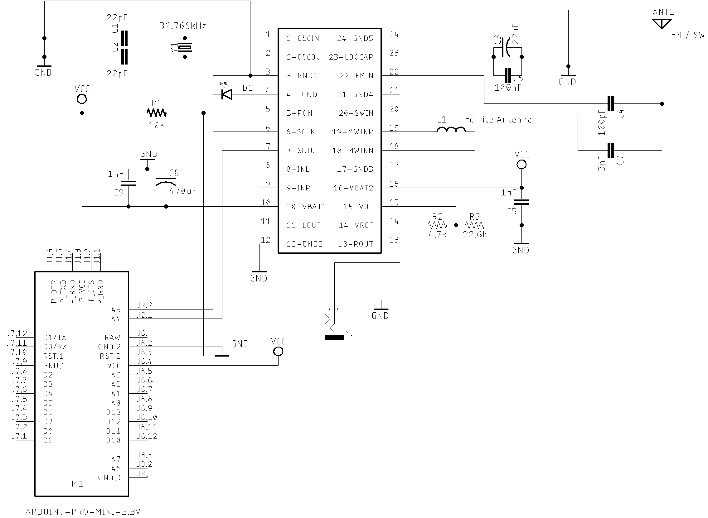
Schematic
The main porpuse of this circuit is testing de AKC695X Arduino Library. It does not intend to be a real receiver for exigent listener. However, it is possible to start with it and after add some improvements. On the other hand, with this simple circuit, the experimenter may be surprised with its performance.
The figure below shows the basic schematic of the AKC695X and Arduino Pro Mini 3.3V, 8MHz.
The schematic below shows the AKC6955 controlled by a standalone ATmega328 with a LCD16X2
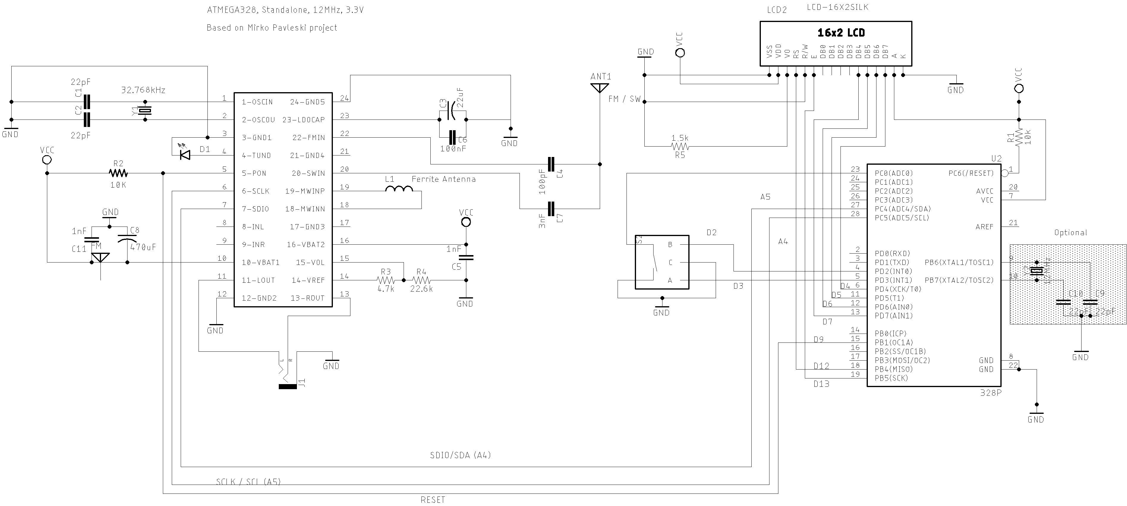
Arduino Pro mini 3.3V/8MHz or standalone Atmega328 and AKC6955, encoder and LCD16x2
| Device name | Device Pin / Description | Arduino Pin |
|---|---|---|
| LCD 16x2 or 20x4 (3.3V) | ||
| D4 | D7 | |
| D5 | D6 | |
| D6 | D5 | |
| D7 | D4 | |
| RS | D12 | |
| E/ENA | D13 | |
| RW & VSS & K (16) | GND | |
| A (15) & VDD | +Vcc | |
| VO (see 20K tripot connection) | ——— | |
| AKC6955 | ||
| RESET (pin 5) | 9 | |
| SDIO (pin 6) | A4 | |
| SCLK (pin 7) | A5 | |
| Encoder | ||
| A | 2 | |
| B | 3 | |
| PUSH BUTTON (encoder) | A0/14 |
Component parts
| Name / Label | Description |
|---|---|
| AKC6955 | SSOP24 DSP receiver from AKC. You also can use AKC5951 (just FM and AM/MW) or AKC6959sx |
| Arduino Board | It can be an Atmega based board, SMT32, ESP32, Attiny or another compatible Arduino board |
| Y1 | 32.32.768kHz or 12MHz crystal oscillator. By default this library uses 32.768kHz. But, you can set it to deal with 12MHz crystal. See API Documentation. |
| C1 and C2 | 22pF Ceramic or Tantalum capacitor |
| C3 | 470uF Electrolytic capacitor |
| C4 | 1nF Ceramic or Tantalum capacitor |
| C4 | 1nF Ceramic or Tantalum capacitor |
| C5 and C8 | 100nF Ceramic or Tantalum capacitor |
| C6 | 100pF Ceramic or Tantalum capacitor |
| C7 | 3nF Ceramic or Tantalum capacitor |
| C9 | 22uF Electrolytic capacitor |
| R1 | 10K resistor |
| R2 | 22K resisto. This value is not critical. Use something closer to 25K |
| R3 | 4.7K resistor. This value is not critical. Use something closer to 5K |
| LED1 | regular LED |
| L1 | Ferrite Rod Coil for LW and MW. It is very common in old medium wave receivers |
AKC695X Pin definitions
The figure and table below show the pin description of the AKC6951 and AKC6955.
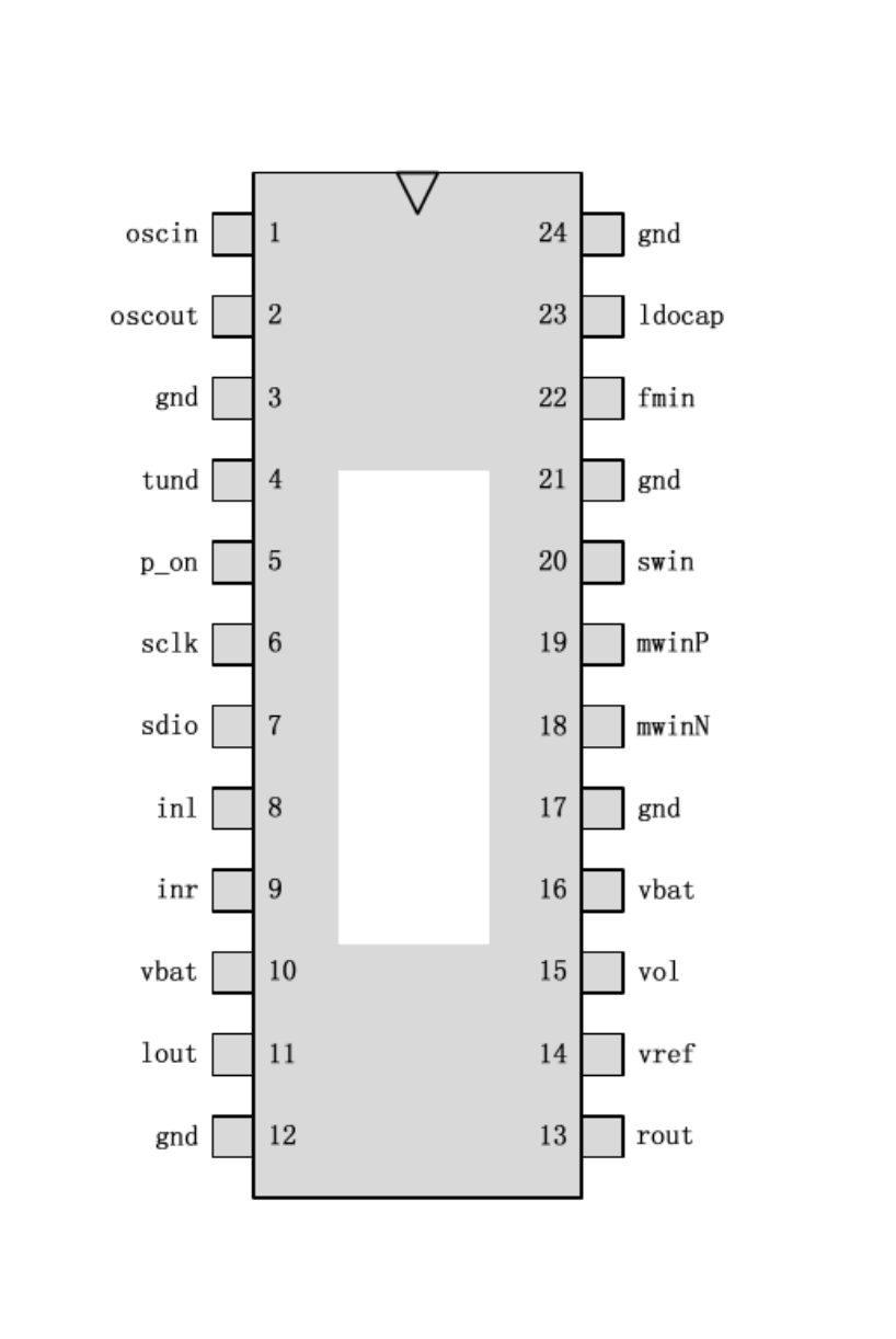
| Pin | Name | Description |
|---|---|---|
| 1 | oscin | Bonding or passive 32.768K 12MHz crystal to ground, or receive an external clock reference signal |
| 2 | oscout | Passive other end connected to the crystal, when connected to an external clock, this pin floating |
| 3 | gnd | Close to ground |
| 4 | tund | Radio lock indicator pin, connected directly to the light emitting diode; Tuning the MCU software when the pin may also be used as a stop sign |
| 5 | p_on | On-chip power switch, high input power chip; the chip down in a low-power standby state, power consumption of approximately 10uA |
| 6 | sclk | 2C clock signal input |
| 7 | sdio | I²C bidirectional data signal input / output |
| 8 | inl | External audio signal input L, proposes to add blocking capacitor 1uF |
| 9 | inr | External audio input signal R, proposes to add blocking capacitor 1uF |
| 10 | vbat | Then the power pins need to pay attention to the nearest ground 0.1uF decoupling capacitance to ground |
| 11 | lout | Left channel audio output |
| 12 | gnd | gnd |
| 13 | rout | Right channel audio output |
| 14 | vref | Precision 1.5V output pin, to provide a baseline volume potentiometer |
| 15 | vol | Variable volume potentiometer connected end, the fixed end of a potentiometer directly connected to VREF, and the other end through a resistor to ground. The resistance ratio of the resistor and potentiometer as 1: 2 |
| 16 | vbat | Then the power pins need to pay attention to the nearest ground 0.1uF decoupling capacitance to ground |
| 17 | gnd | Close to ground |
| 18 | mwinN | MW and LW differential input signal |
| 19 | mwinP | MW and LW differential input signal |
| 20 | swin | Shortwave signal input terminal, note add blocking capacitor recommended 3nF |
| 21 | gnd | Close to ground |
| 22 | fmin | FM radio frequency signal input terminal, note add blocking capacitor, 100pF recommendations |
| 23 | ldocap | Internal LDO output pin, nearest the need decoupling capacitors, recommendations 47uF |
| 24 | gnd | Close to ground |
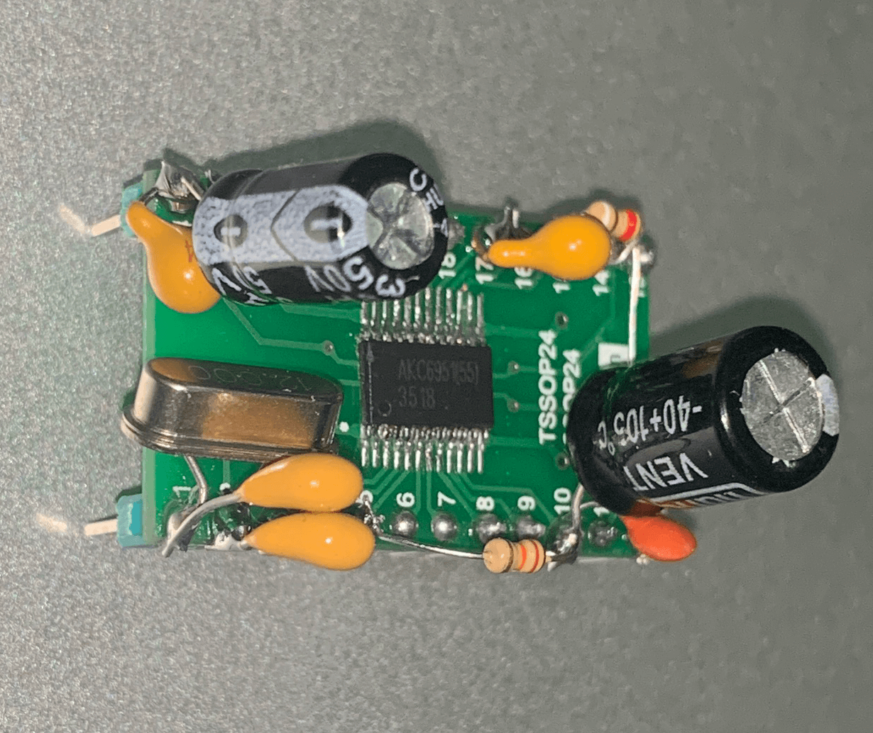
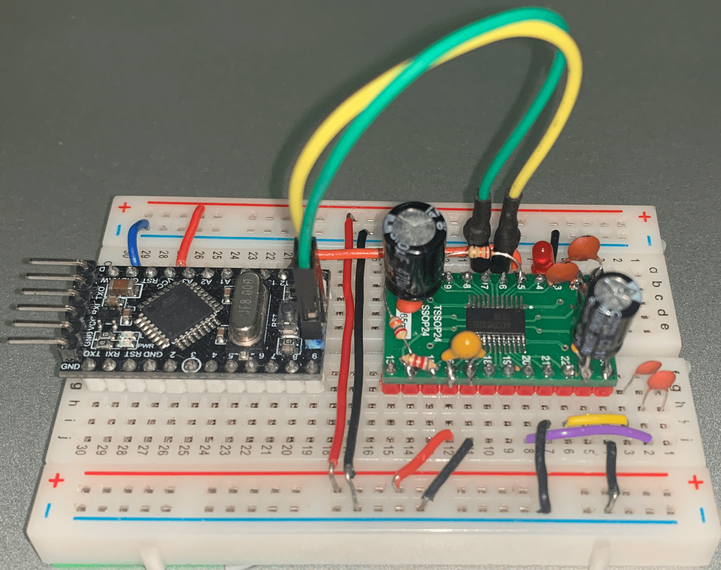
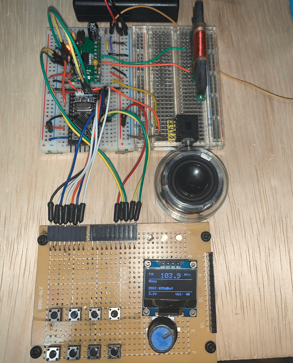
Prototype Photos

Videos
Receivers based on AKC695X / M695X
Troy reviews the Audiomax SRW-710S Full Review of the Tivdio V115 AM FM Shortwave portable receiver
Third-party projects using this library
References
- AM-SW-FM radio by DSP radio chip version 2
- Radio, yes AM-SW-FM radio by DSP radio chip
- AKC6955-M6955–DSP-radio-with-full-colour-LCD