RDA5807 Arduino Library
It is a cross-platform Arduino library for the RDA5807 and RDA7088 family of devices from RDA Microelectronics. This library is compatible with official Arduino boards, ATtiny, STM32, ESP32, and more. Utilizing the I2C protocol, it provides an easier interface for controlling the RDA5807 device. The library was developed based on the ‘RDA5807MS - SINGLE-CHIP BROADCAST FM RADIO TUNER - Rev.1.1–Aug.2015’ and the ‘RDA5807FP - SINGLE-CHIP BROADCAST FM RADIO TUNER’ documentation from RDA Microelectronics. Please refer to the table of contents below to make the best use of this documentation.
This library can be freely distributed using the MIT Free Software model. It means you can copy, modify, merge, publish, distribute, sublicense, and/or sell copies of the Software. See MIT License for more details.
Copyright (c) 2019 Ricardo Lima Caratti.
Contact: pu2clr@gmail.com.
Donate
If you find this library useful and would like to support its continued development, you may optionally make a donation. Donations help cover the cost of components, modules, and laboratory testing used in the maintenance and improvement of this open-source project. Donations are entirely voluntary and do not grant any special product, service, warranty, support, or development priority. Please note that this project is maintained on a voluntary basis, and the author makes no commitment regarding schedules or deadlines for future releases, updates, or feature implementations. Click here to donate or use the QR code below.
About Me
I hold a Master’s degree in Educational Technology from the Federal University of Ceará, where I delved into the ways technology can enhance learning experiences. My passion for computer science led me to specialize in it, focusing on Distributed Systems Development with an Object-Oriented approach, at the University of Brasília. My academic journey began with a Bachelor’s degree in Information Systems from the União Pioneira de Integração Social (UPIS-Brasília). Outside the classroom, my main hobbies are electronics and Amateur Radio.
Contents
- Preface
- RDA5807 family devices and RDA5807 Arduino Library
- Library Installation
- Minimal receiver implementation with this library
- Examples summary
- Boards where this library has been tested
- RDA5807M breakout
- RDA5807FP and RDA7088 standalone IC
- API Documentation
- MIT License
- Basic Schematic
- All Schematics, photos and videos
- Storing data into the EEPROM
- Extending RDA5807 class
- LilyGO/T-Embed and RDA5807 setup
- Source code - Arduino Sketches
- Videos about this library
Attention
- The RDA5807 device can work safaty from 2.7 to 3.3V. Be aware that some Arduino board oparates with 5V instead of 3.3V (for example: Arduino Uno and Arduino Nano). A wrong setup can make the system unstable or damage the RDA5807 device. Preferably use an Arduino or other boards like ESP32 and ESP8266 that work with 3.3V voltage. If you are not using a 3.3V version of board, you must use a kind of 5V to 3.3V converter to feed the RDA5807 device and to send signal to SCLK and SDIO/SDA pins. In my experiments, I used an Arduino Nano (5V) and fed the RDA5807 with 3.3V (from the Nano. See the Pin 3.3V of the Arduino). It has worked. However, this is at your own risk.
Preface
The RDA5807 is an FM DSP integrated circuit receiver that operates in the 50 to 115MHz range and includes support for a low-noise amplifier. This device requires fewer external components compared to other similar products and offers features such as RDS/RBDS functionalities, direct auto gain control (AGC), and real-time adaptive noise cancellation. The PU2CLR RDA5807 Arduino Library was developed to maximize the functionalities of this device. The primary motivations for developing this library were to understand the operational aspects of this receiver and to share this knowledge. Currently, the library has over 80 functions implemented. I hope this work will prove useful to electronics experimenters and hobbyists.
This documentation reflects the author’s understanding of the IC RDA5807 family’s operation. With that said, there may be inaccuracies or incorrect information. If you find any errors, please bring them to my attention.
Please, check the API Documentation for more details.
Your support is important.
If you want to support this library development, consider joining this project via Github. Alternatively, make suggestions on new features and report errors if you find them. Thank you!
There is a Facebook group called DSP receivers for hobbyists where the purpose is exchanging experiences with projects based on RDA5807 IC devices.
RDA5807 family devices and RDA5807 Arduino Library
This library has been successfully tested on RDA5807M and RDA5807FP devices. The videos below show some examples of using this library with RDA5807M and RDA5807FP.
FM receiver based on RDA5807 and LilyGO/T-Embed panel
RDS and RDA5807 using this library
RDS - TFT Display
RDA5807 main features implemented by this library
- 76–108 MHz
- Seek tuning
- Automatic frequency control (AFC)
- Automatic gain control (AGC)
- Programmable de-emphasis (50/75 μs)
- Adaptive noise suppression
- Volume control
- Bass
- Mute control
- Mono/Stereo control
- RDS/RBDS Processor
- I2S Digital Audio (RDA5807FP)
- LNA (Low Noise Amplifiers)
- Softmute
- Stereo / Mono
- Step
- The Sketch RDA5807_00_CIRCUIT_TEST uses the main functions implemented in this library
- The examples folder can guide you in building your own receiver
- See API documentation
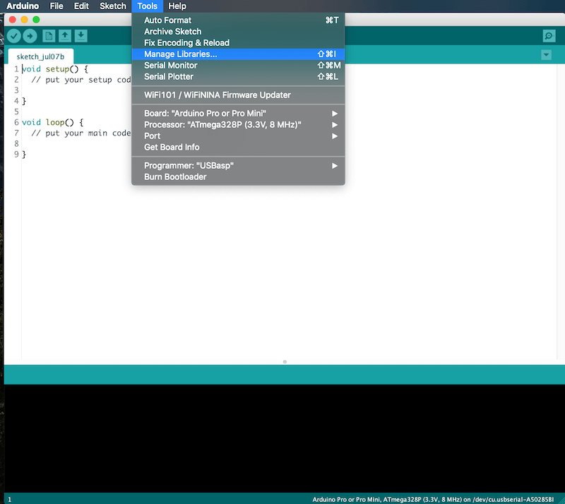
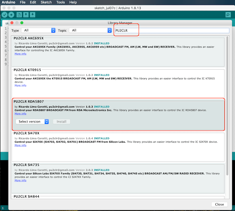
Library Installation
The easiest method to install this library is via your Arduino IDE. All you have to do is:
- Select Tools menu;
- Select Manage Libraries option;
- In the text box (top windows), type PU2CLR or RDA5807;
- Select the PU2CLR RDA5807.
The images below show how you can install this library via your Arduino IDE from Manage Libraries tool.
Installing via the repository
With this approach, you will have the most current version of the library. However, it may not be the most stable version. This is because the current version is always in development. Prefer releases. Do you need some old version (release) of this library? If yes, check here.
First, you have to download this library in zip format.
After, unzip the RDA5807-master.zip file in your Arduino Library folder.
- On Windows: “My Documents\Arduino\libraries”
- On MAC OS: ˜/Documents/Arduino/libraries
- On Linux: ˜/home/Arduino/libraries
Installing the most current version via arduino-cli
The commands below Install the latest version of the PU2CLR RDA5807 Arduino Library from github. As said before, unlike a release (installed from Arduino IDE) this method installs the current version of the PU2CLR RDA5807 Arduino Library (latest modifications even if not yet released).
On macOS or Linux
curl -fsSL https://raw.githubusercontent.com/arduino/arduino-cli/master/install.sh | sh
export ARDUINO_LIBRARY_ENABLE_UNSAFE_INSTALL=true
./bin/arduino-cli lib install --git-url https://github.com/pu2clr/RDA5807
On Windows 10 or 11
Run the command shell (cmd / Command Prompt) and follow the steps below.
echo off
curl -fsSL https://downloads.arduino.cc/arduino-cli/arduino-cli_latest_Windows_64bit.zip --output arduinocli.zip
tar -xf arduinocli.zip
set ARDUINO_LIBRARY_ENABLE_UNSAFE_INSTALL=true
.\arduino-cli lib install --git-url https://github.com/pu2clr/RDA5807
How to use the RDA5807 Arduino Library in your sketch
The following source-code snippet shows a common way of using the RDA5807 library in your application. Click here to know about all the functions integrated in this library.
#include <RDA5807.h>

RDA5807 rx;

void setup() {
    .
    .
    .
    // Start your receiver here
    rx.setup();
    rx.setVolume(6);
    rx.setFrequency(some_frequency); // Example 10390 for 103,9 MHz
    .
    .
    .
}

void loop() {
    //  Control your receiver here
    .
    .
    .
}
Minimal receiver implementation with this library
The code below shows the minimal implementation using this library.
#include <RDA5807.h>
RDA5807 rx;
void setup() {
  rx.setup(); // Starts the receiver with default parameters
  rx.setFrequency(10390); // Tunes in 103.9 MHz  - Switch to your local favorite station
}
void loop() {

}
A minimalist receiver implementation with two pushbuttons
The following code illustrates a minimalist implementation of a receiver based on RDA5807 and this library. For this receiver, the user has two pushbuttons to tune station (Seek Up and Seek Down).
#include <RDA5807.h> // It is a minimal receicer with two push buttons (ATmega328 - Uno, Nano etc)
RDA5807 rx;
void setup() {
  pinMode(4, INPUT_PULLUP); // Arduino pin 4 - Seek station down
  pinMode(5, INPUT_PULLUP); // Arduino pin 5 - Seek station up
  rx.setup(); // Starts the receiver with default parameters
  rx.setFrequency(10390); // Tunes in 103.9 MHz  - Switch to your local favorite station
}
void loop() {
  if (digitalRead(4) == LOW) rx.seek(RDA_SEEK_WRAP,RDA_SEEK_DOWN);
  if (digitalRead(5) == LOW) rx.seek(RDA_SEEK_WRAP,RDA_SEEK_UP);
  delay(200);
}
You can use the sketch above with the circuit shown below.
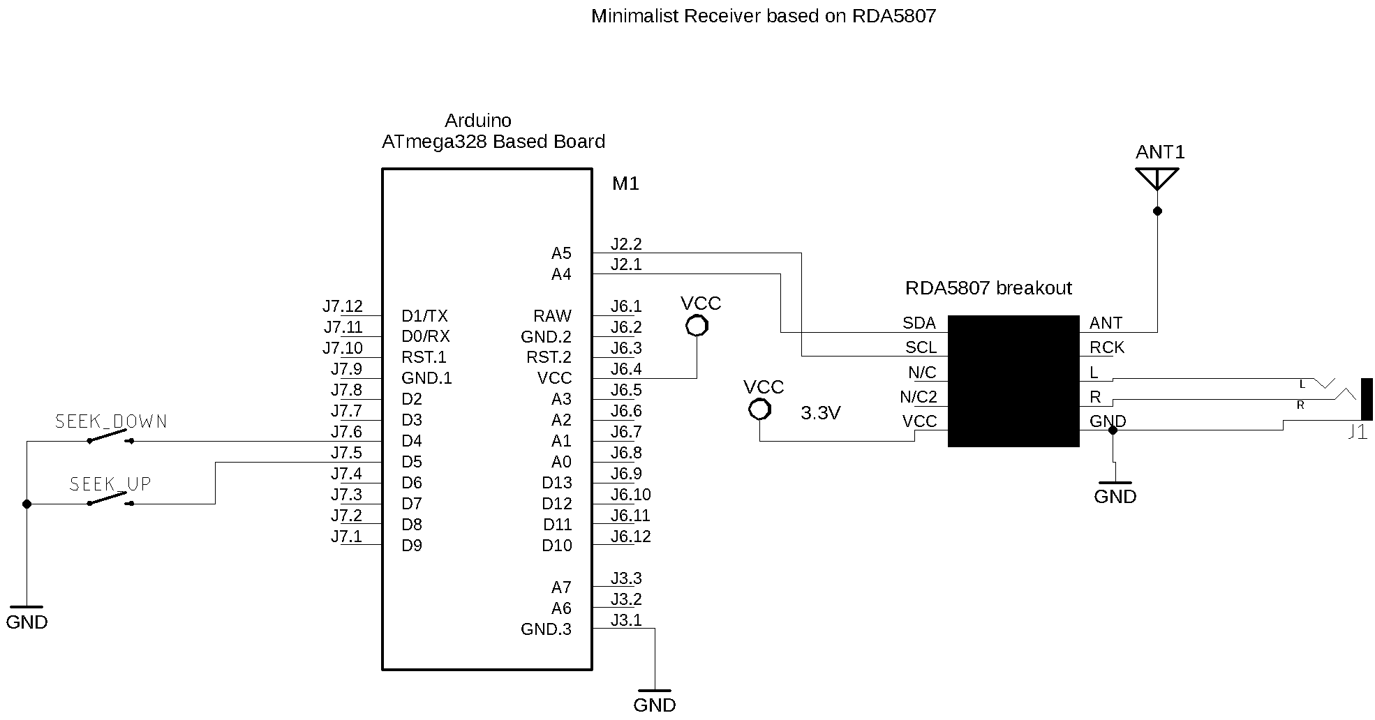
See also other schematics with RDA5807.
MINIMALIST RECEIVER WITH RDA5807 ARDUINO LIBRARY
Examples summary
The following table shows the main examples implemented in this library. These examples can guide you to build your own receiver.
| Sketch Name | Description |
|---|---|
| RDA5807_00_CIRCUIT_TEST | Useful to check the circuit and many functions implemented in this library |
| RDA5807_00_MINIMAL_RECEIVER | It is a minimal receicer with two push buttons (ATmega328 - Uno, Nano etc) |
| RDA5807_01_SERIAL_MONITOR/ RDA5807_01_ALL_TEST_SERIAL_MONITOR |
More about Tune, Volume, Seek and RDS features |
| RDA5807_01_SERIAL_MONITOR/ RDA5807_01_RDS_TEST_SERIAL_MONITOR |
Test RDS functions using Serial Monitor |
| RDA5807_01_SERIAL_MONITOR/ RDA5807_02_ESP32 |
Test and validation of RDA5807 on ESP32 board |
| RDA5807_01_SERIAL_MONITOR/ RDA5807_03_STM32 |
Test and validation of RDA5807 on STM32 board |
| RDA5807_02_TFT_display | This sketch uses an Arduino Pro Mini, 3.3V (8MZ) with a SPI TFT ST7735 1.8 |
| RDA5807_03_ATTINY_84_85 | Test and validation of RDA5807 on ATtiny84 device |
| RDA5807_04_NOKIA5110 | This sketch uses an Arduino Nano with NOKIA 5110 display |
| RDA5807_05_LCD16X02 | This sketch uses an Arduino Nano with LCD16X02 DISPLAY |
| RDA5807_05_LCD16X02_ESP32 | This sketch uses an ESP32 with LCD16X02 DISPLAY |
| RDA5807_05_LCD16X02_ESP32_I2S | I2S setup - This sketch uses an ESP32 with LCD16X02 DISPLAY and MAX98357A I2S setup |
| RDA5807_06_UNO_TM1638 | This sketch drives the RDA5807 FM receiver and TM1638 (seven-segment display control) |
| Arduino Nano and OLED with Tiny4kOLED library | Nano and OLED implementation V1 |
| Arduino Nano and OLED (Adafruit_GFX and Adafruit_SSD1306) | This sketch works on Atmega328 and LGT8FX based board. It is a I2C OLED setup |
| LilyGO/T-Embed and RDA5807 setup | This sketch was an adaptation of the Volos’s sketch and uses PU2CLR RDA5807 Arduino Library with LilyGO T-Embed. |
See the folder examples do know more
Boards where this library has been tested
This library can be useful to develop cross-platform software. So far, it has been successfully tested on the architectures shown below. Please, pay attention to the pins used for I2C communication.
| Board | Need voltage converter | I²C Pins | Features | |
|---|---|---|---|---|
| 1 | Arduino Pro Mini 3.3V 8MHz | No | A4 and A5 | More… |
| 2 | Mega 2560 Pro | Yes | 20 and 21 | More… |
| 3 | ESP WEMOS LOLIN32 | No | GPIO21 and GPIO22 [4] | More… |
| 4 | ESP32 Dev Module | No | GPIO21 and GPIO22 [4] | More… |
| 5 | ESP32 Wrover Module | No | GPIO21 and GPIO22 [4] | More… |
| 6 | ESP8266 | No | GPIO4 and GPIO5 | More… |
| 7 | Arduino UNO | Yes | A4 and A5 | More… |
| 8 | Arduino NANO ATmega 328 | Yes | A4 and A5 | More… |
| 9 | Arduino NANO ATmega 168 | Yes | A4 and A5 | More… |
| 10 | Arduino NANO 33 IoT | No [6] | A4 and A5 | More… |
| 11 | Arduino Yún / ATmega-32u4 | Yes | 2 and 3 | More… |
| 12 | ATtiny84 | No | 7 and 8 | More… |
| 13 | ATtiny85 | No | 5 and 7 | More… |
| 14 | Arduino DUE | No | 2 and 3 | More… |
| 15 | BlueDuino 3.3V (ATmega-32u4) | No | 2 and 3 | More… |
| 16 | Arduino Mini Pro 5V 16Mhz | Yes | 2 and 3 | More… |
| 17 | STM32F746G-DISCO | No | - | More… |
| 18 | STM32F103 Series | No | PB6 (SCL) and PB7(SDA) | More… |
| 19 | STM32F411 Series | No | PB6 (SCL) and PB7(SDA) | More… |
| 20 | Raspberry Pi Pico | No | GP0 (0) and GP1 (1) | More… |
| 21 | WeAct Studio RP2040 Pico | No | GP0 (0) and GP1 (1) | More… |
| 22 | Seeeduino XIAO | No | A4 and A5 | More… |
| 23 | Teensy 3.1 | No | A4 and A5 | More… |
| 24 | Teensy 4.1 | No | A4 and A5 | More… |
| 25 | Atmega8 | No | PC4 and PC5 | More… |
| 26 | Atmega32 | No | PC1 and PC0 | More… |
| 27 | Atmega128 | No | PC1 and PC0 | More… |
| 28 | LGT8F328P | No | A4 and A5 | More… |
| 29 | LUATOS ESP32C3 | No | GPIO4 and GPIO5 | More… |
- More about ESP boards on ESPRESSIF Development Boards.
- More about BlueDuino on Seed.
- On Arduino.cc you can see the technical specification about many board.
- It seams that in some ESP32 board, the I²C bus is not configured properly by default. However, you can set almost any pin on ESP32 to setup I²C capabilities. All you have to do is call Wire.begin(SDA, SCL); where SDA and SCL are the ESP32 GPIO pins. See the folder examples to check how to use ESP32 devices.
- Arduino Nano 33 BLE only supports 3.3V I/Os and is NOT 5V tolerant so please make sure you are not directly connecting 5V signals to this board or it will be damaged. Also, as opposed to Arduino Nano boards that support 5V operation, the 5V pin does NOT supply voltage but is rather connected, through a jumper, to the USB power input.
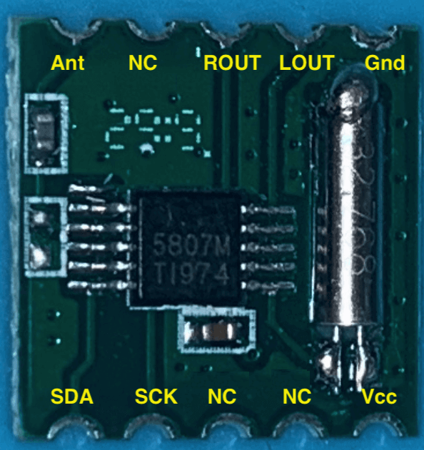
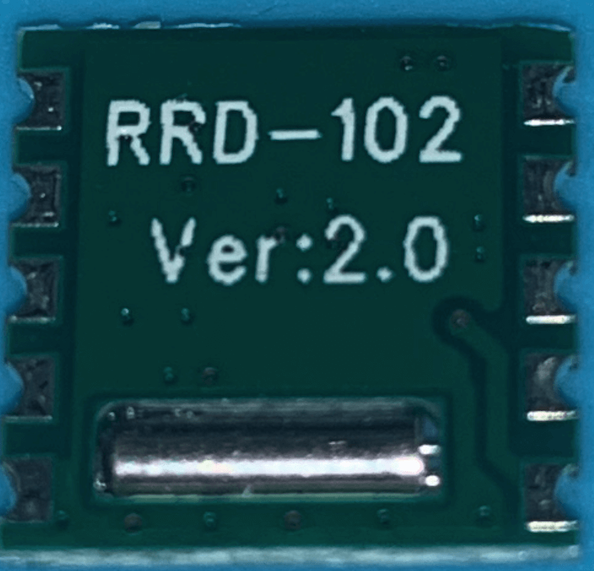
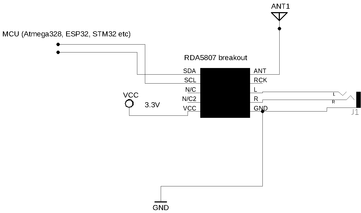
RDA5807M breakout
The photos below show a Breakout that uses the RDA5807M.
Front side
Back side
- Judging by some documentations found on the Internet, some breakouts based on RDA5807M have GPIO2, GPIO3 and RCLK functions. Judiging by the “RDA microelectronics RDA5807MS - SINGLE-CHIP BROADCAST FM RADIO TUNER - Rev.1.1–Aug.2015”, the RDA5807MS pinout does not have these functions. These documentations is still not clear to the author of this library. So, if you want to use the GPIO features of the RDA5807 architecture, please, prefer the RDA5807FP device (see it below).
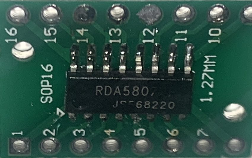
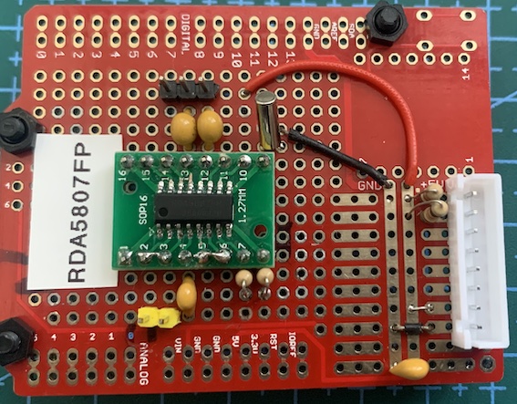
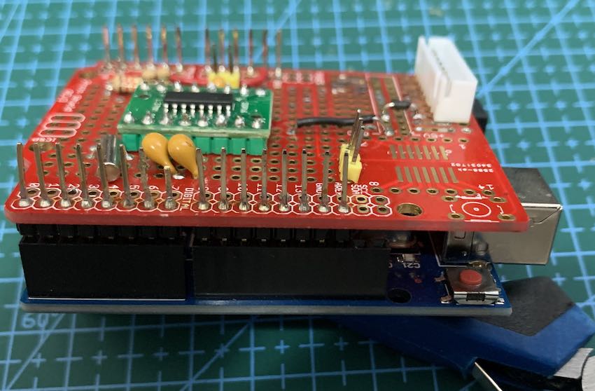
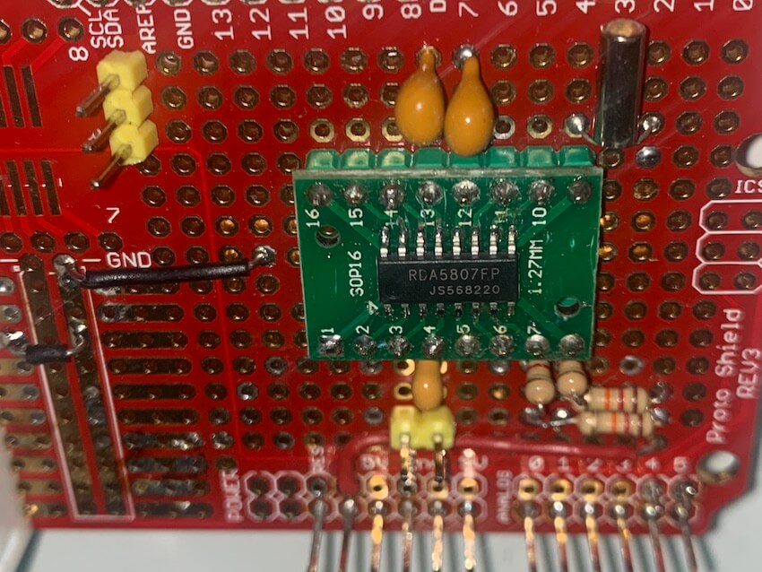
RDA5807FP and RDA7088 standalone IC
If you are using the standalone RDA5807FP you must add some parts to make it work. In my opinion, there is no big reasons to use the RDA5807FP instead of the RDA5807M breakout in most applications. I think the most important situations are the possibility to use the digital audio configuration via I2S protocol or GPIO setup (Stereo indicator, interrupt etc). This library has function to deal with I2S and GPIO.
The RDA7088 has the same RDA5807FP pinout. However, I have noticed that some functions available in this library do not work prorpely. For example: RDS, Seek and Stereo functions have not worked on RDA7088 during tests with RDA5807 Arduino Library. In contrast, all functions implemented in this library work well on RDA5807FP. Prefer the RDA5807FP.
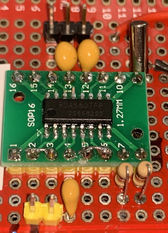
The photo below shows the RDA5807FP on a SOP16 board adapter.
RDA5807FP PINOUT
The image below shows the RDA5807FP pinout.
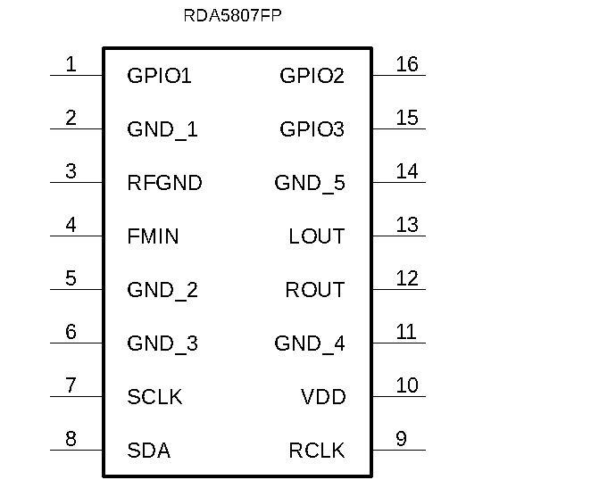
| PIN | Label | Description |
|---|---|---|
| 1 | GPIO1 | General purpose input/output |
| 2 | GND_1 | Ground. Must be connected to ground |
| 3 | RFGND | RF Ground. Must be connected to the ground or a special RF ground |
| 4 | FMIN | FM signal input - Antenna |
| 5 | GND_2 | Ground. Must be connected to ground |
| 6 | GND_3 | Ground. Must be connected to ground |
| 7 | SCLK | I2C clock |
| 8 | SDA | I2C SDA/SDIO |
| 9 | RCLK | 32.768kHz pasive crystal |
| 10 | VDD | 3.3V power supply |
| 11 | GND_4 | Ground. Must be connected to ground |
| 12 | ROUT | Right audio output |
| 13 | LOUT | Left audio output |
| 14 | GND_5 | Ground. Must be connected to ground |
| 15 | GPIO3 | General purpose input/output and stereo indicator |
| 16 | GPIO2 | General purpose input/output |
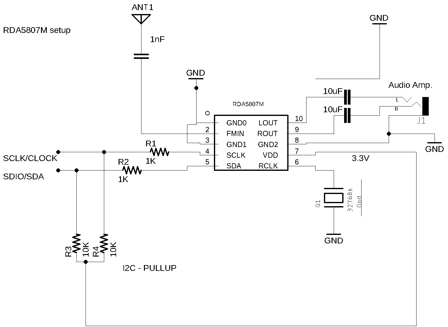
The two photos below shows the standalone RDA5807FP IC mounted on a homebrew board.
The schematic below shows the basic RDA5807FP setup.
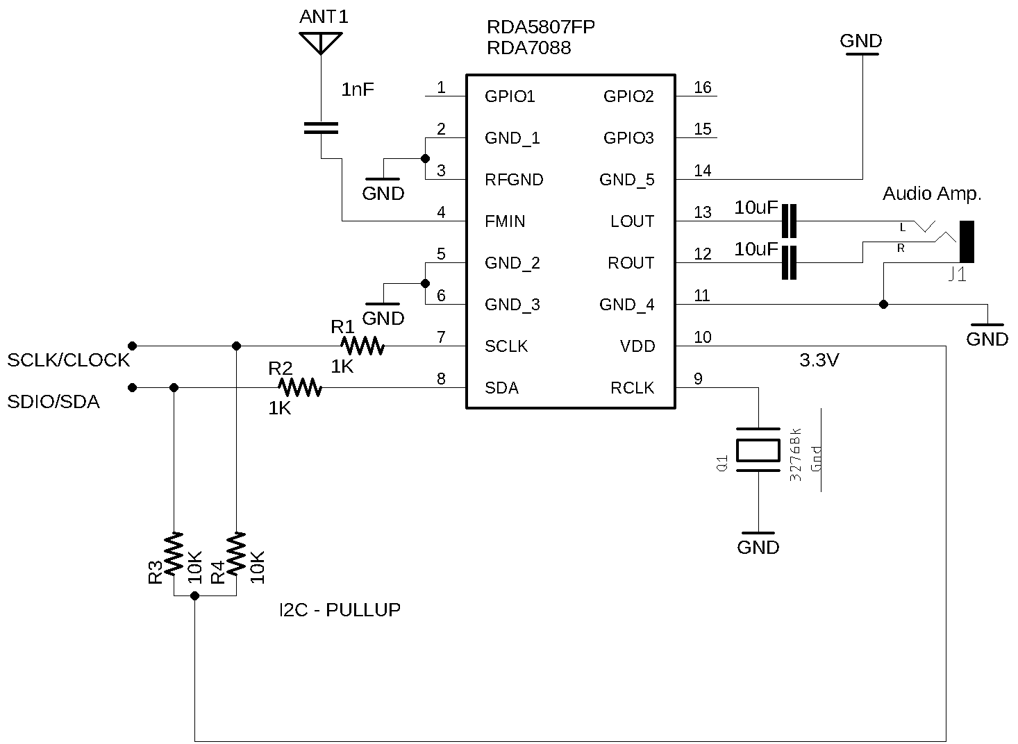
| Components | Value |
|---|---|
| R1 | 1K |
| R2 | 1K |
| R3 | 8 ~ 12K |
| R4 | 8 ~ 12K |
| C1 | 1nF (FMIN) |
| C2 and C3 | 4,7 ~ 10uF tantalum capacitor (stereo audio output) |
| Q1 | 32768 kHz passive crystal oscillator |
| J1 | Audio stereo jack |
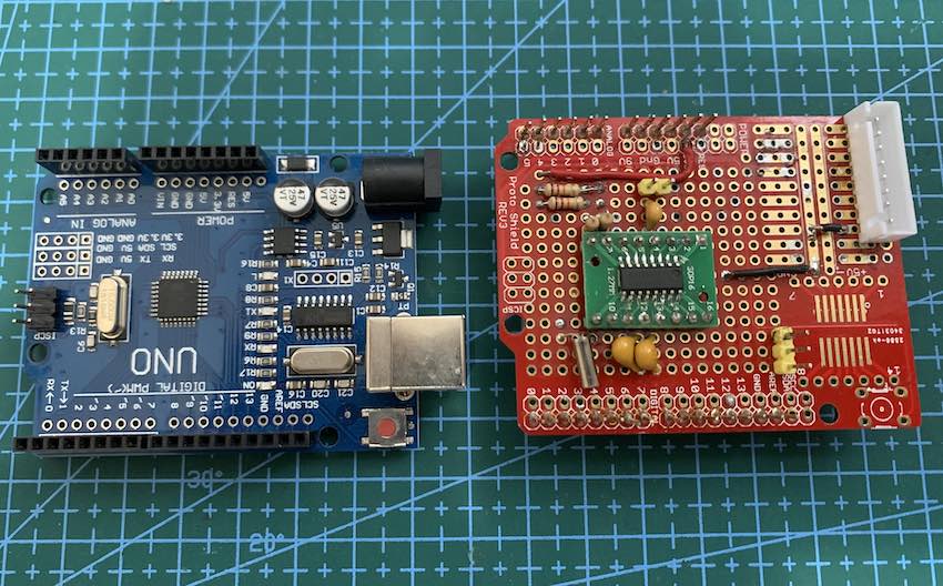
The RDA5807FP on an Arduino Uno adapter
The photos below show the RDA5807FP setup on a Arduino Uno board adapter.
Video about the RDA5807, Arduino Uno and 7-segment display based on TM1638 device
MIT License
Copyright (c) 2019 Ricardo Lima Caratti
Permission is hereby granted, free of charge, to any person obtaining a copy of this software and associated documentation files (the “Software”), to deal in the Software without restriction, including without limitation the rights to use, copy, modify, merge, publish, distribute, sublicense, and/or sell copies of the Software, and to permit persons to whom the Software is furnished to do so, subject to the following conditions:
The above copyright notice and this permission notice shall be included in all copies or substantial portions of the Software.
THE SOFTWARE IS PROVIDED “AS IS”, WITHOUT WARRANTY OF ANY KIND, EXPRESS OR IMPLIED, INCLUDING BUT NOT LIMITED TO THE WARRANTIES OF MERCHANTABILITY, FITNESS FOR A PARTICULAR PURPOSE AND NONINFRINGEMENT. IN NO EVENT SHALL THE AUTHORS OR COPYRIGHT HOLDERS BE LIABLE FOR ANY CLAIM, DAMAGES OR OTHER LIABILITY, WHETHER IN AN ACTION OF CONTRACT, TORT OR OTHERWISE, ARISING FROM, OUT OF OR IN CONNECTION WITH THE SOFTWARE OR THE USE OR OTHER DEALINGS IN THE SOFTWARE.
Schematic
The circuits below can help you to connect the arduino based board to the RDA5807 version you are using. In general, the RDA5807 can be found in kit or breakout form on Aliexpress, Amazon, eBay etc.
RDA5807M Breakout setup
RDA5807M standalone IC setup (without breakout)
RDA5807FP standalone IC setup
Arduino UNO, Pro mini or other based on ATmega 328 wireup.
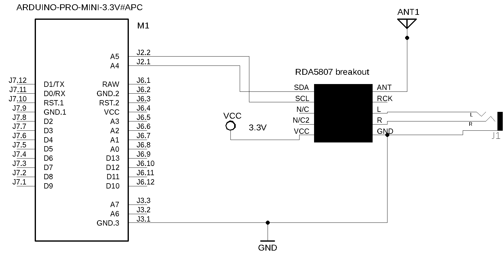
| RDA5807 / Description | Arduino Pin |
|---|---|
| VCC | 3.3V |
| SDA / SDIO | A4 |
| SCL / SCLK | A5 |
Arduino, TFT7735 display and Push Buttons wireup.
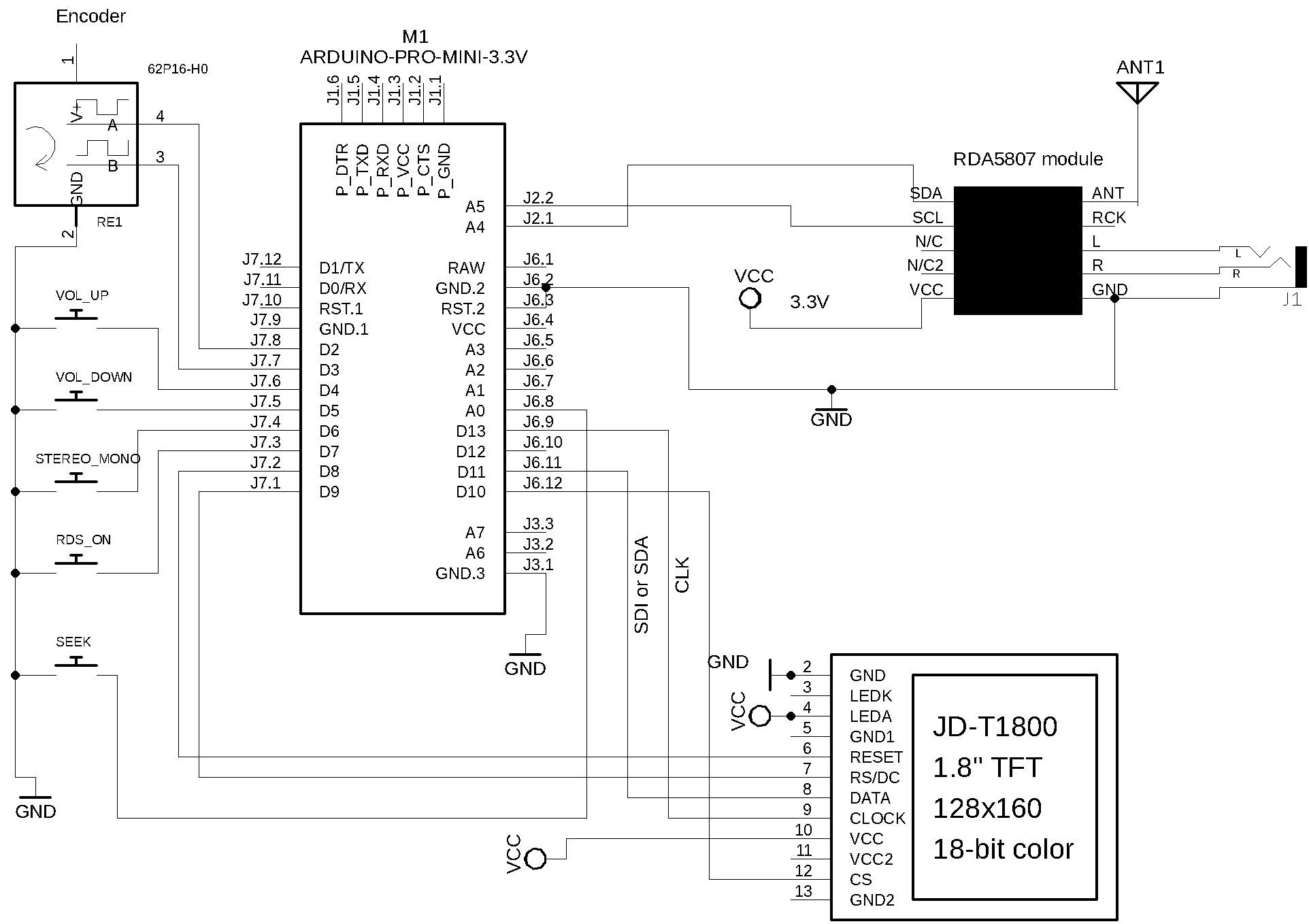
Arduino UNO, Nano or other based on Atmega328 and SPI TFT ST7735 1.8” wireup
| Device name | Device Pin / Description | Arduino Pin |
|---|---|---|
| Display TFT | ||
| RST (RESET) | 8 | |
| RS or DC | 9 | |
| CS or SS | 10 | |
| SDI | 11 | |
| CLK | 13 | |
| RDA5807 | ||
| VCC | 3.3V | |
| SDIO (pin 8) | A4 | |
| SCLK (pin 7) | A5 | |
| Buttons | ||
| Volume Up | 4 | |
| Volume Down | 5 | |
| Stereo/Mono | 6 | |
| RDS ON/off | 7 | |
| SEEK (encoder button) | A0/14 | |
| Encoder | ||
| A | 2 | |
| B | 3 |
RDA5807 breakout, ATtiny84, Encoder and Buttons schematic
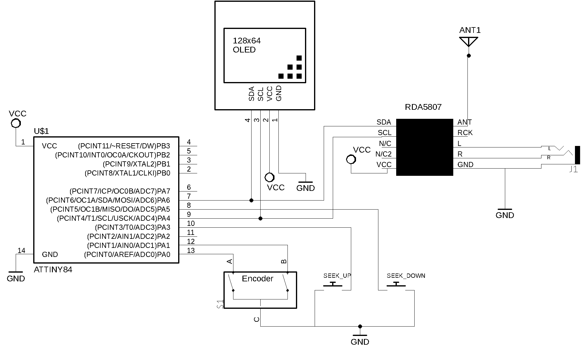
RDA5807 breakout, ATtiny84, Encoder and Buttons wireup
| RDA5807 pin | Attiny84 REF pin | Physical pin |
|---|---|---|
| SEEK_UP | 3 | 10 |
| SEEK_DOWN | 5 | 8 |
| ENCODER_PIN_A | 0 | 13 |
| ENCODER_PIN_B | 1 | 12 |
| SDIO / SDA | SDA | 7 |
| SCLK / CLK | SCL | 9 |
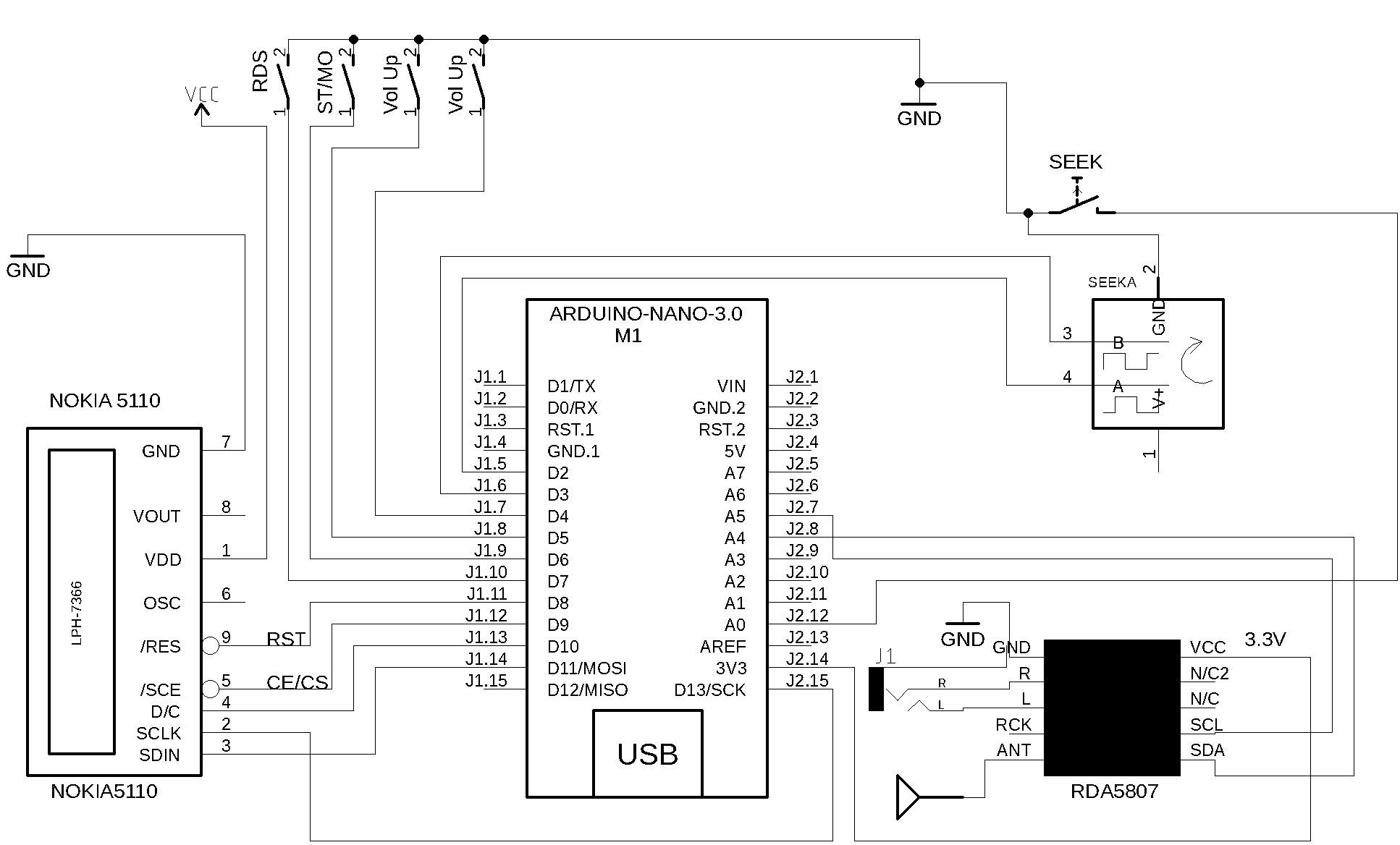
RDA5807 breakout, Arduino Nano and Nokia 5110 display wireup
| Device name | Nokia 5110 | Arduino |
|---|---|---|
| NOKIA 5110 | Pin function | Nano Pin |
| (1) RST (RESET) | 8 | |
| (2) CE or CS | 9 | |
| (3) DC or DO | 10 | |
| (4) DIN or DI or MOSI | 11 | |
| (5) CLK | 13 | |
| (6) VCC (3V-5V) | +VCC | |
| (7) BL/DL/LIGHT | +VCC | |
| (8) GND | GND | |
| RDA5807 | Pin Function | |
| VCC | 3.3V | |
| SDIO (pin 8) | A4 | |
| SCLK (pin 7) | A5 | |
| Buttons | ||
| Volume Up | 4 | |
| Volume Down | 5 | |
| Stereo/Mono | 6 | |
| RDS ON/off | 7 | |
| SEEK (encoder button) | A0/14 | |
| Encoder | ||
| A | 2 | |
| B | 3 |
Arduino Nano, RDA5807 and Nokia 5110 setup on Breadboard

RDA5807 breakout, Arduino Nano and LCD16X02 display wireup
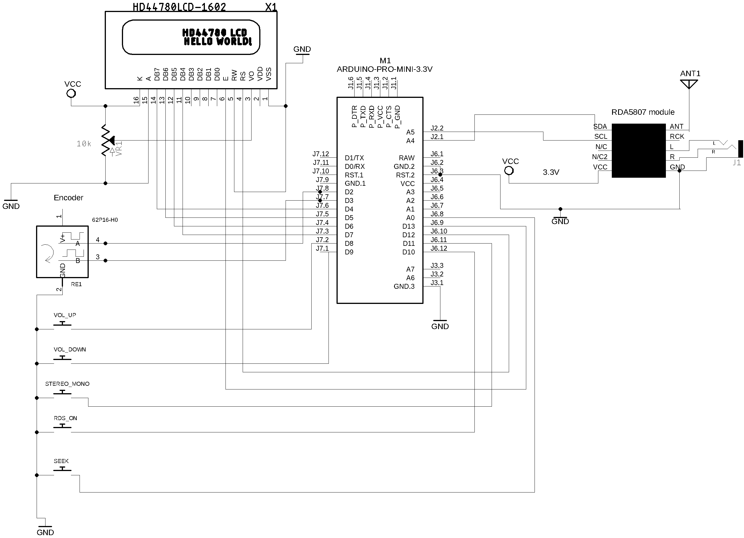
| Device name | Device Pin / Description | Arduino Pin |
|---|---|---|
| LCD 16x2 or 20x4 | ||
| D4 | D7 | |
| D5 | D6 | |
| D6 | D5 | |
| D7 | D4 | |
| RS | D12 | |
| E/ENA | D13 | |
| RW & VSS & K (16) | GND | |
| A (15) & VDD | +Vcc | |
| RDA5807 | ||
| VCC | 3.3V | |
| SDIO (pin 8) | A4 | |
| SCLK (pin 7) | A5 | |
| Buttons | ||
| Volume Up | 8 | |
| Volume Down | 9 | |
| Stereo/Mono | 10 | |
| RDS ON/off | 11 | |
| SEEK (encoder button) | D14/A0 | |
| Encoder | ||
| A | 2 | |
| B | 3 |
RDA5807FP setup, ESP32 and LCD16X02 display wireup
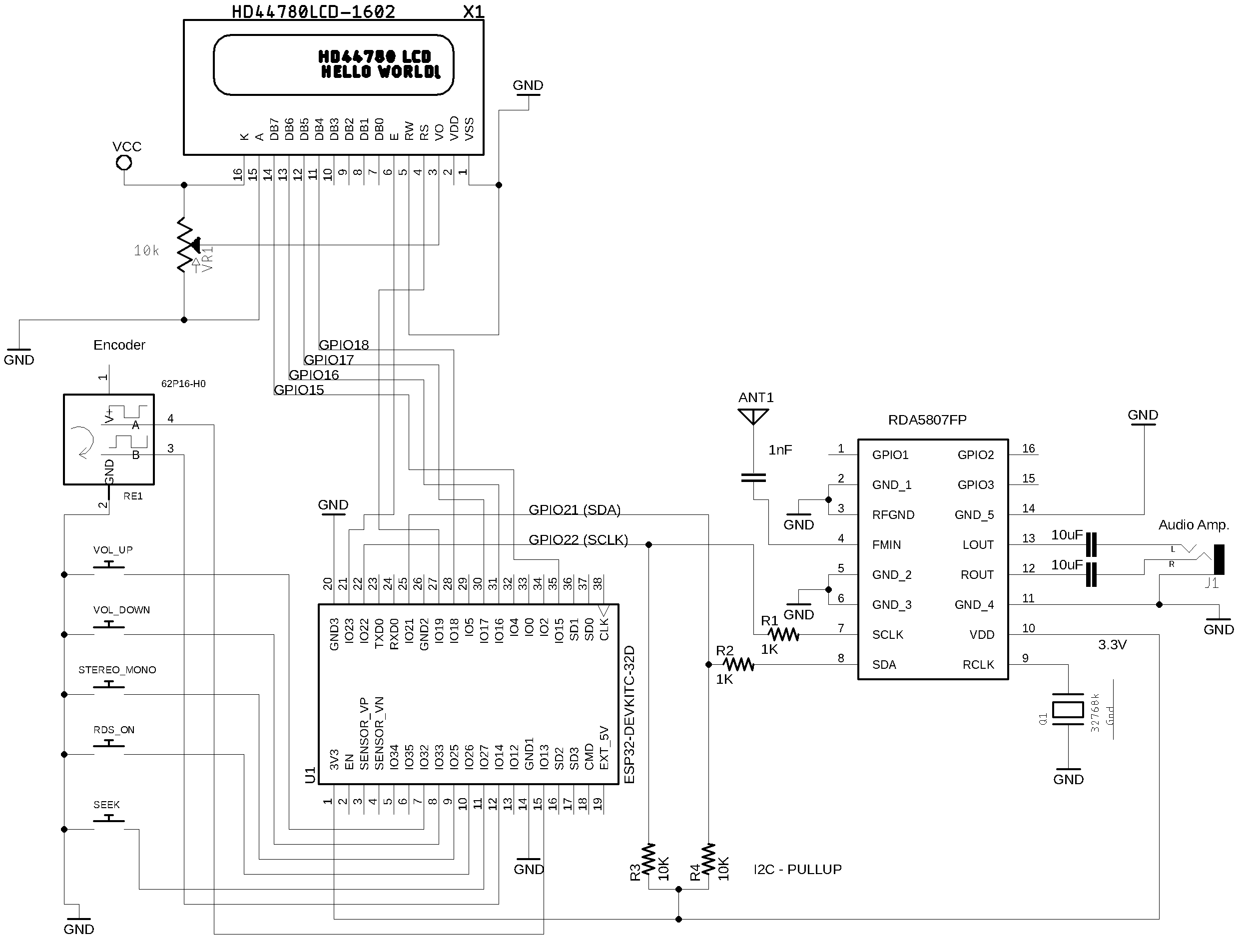
Wire up ESP32 Dev Module, RDA5807 and LCD16x02 or LCD16x04
| Device name | Device Pin / Description | Arduino Pin |
|---|---|---|
| LCD 16x2 or 20x4 | ||
| D4 | GPIO18 | |
| D5 | GPIO17 | |
| D6 | GPIO16 | |
| D7 | GPIO15 | |
| RS | GPIO19 | |
| E/ENA | GPIO23 | |
| RW & VSS & K (16) | GND | |
| A (15) & VDD | +Vcc | |
| RDA5807FP (See schematic) | ||
| VCC | 3.3V | |
| SDIO / SDA (pin 8) | GPIO21 | |
| SCLK (pin 7) | GPIO22 | |
| Buttons | ||
| Volume Up | GPIO32 | |
| Volume Down | GPIO33 | |
| Stereo/Mono | GPIO25 | |
| RDS On/Off | GPIO26 | |
| Encoder | ||
| A | GPIO13 | |
| B | GPIO14 | |
| PUSH BUTTON (encoder) | GPIO27 |
ATTENTION: Be guided by the ESP32 IO/GPIO pins.
Storing Data into the EEPROM
The EEPROM has a lifespan of around 100,000 write/erase cycles. According to the “Atmel” datasheet, page 19, “The Atmel® ATmega328P contains 1Kbyte of data EEPROM memory. It is organized as a separate data space, in which single bytes can be read and written. The EEPROM has an endurance of at least 100,000 write/erase cycles.” Consequently, writing data to the EEPROM every time the system status changes could severely limit the application’s lifespan. To address this issue, several strategies can be used to optimize EEPROM writes.
Approach
This approach involves storing data only when crucial system statuses change. The aim is to minimize unnecessary writes to the EEPROM.
Steps:
- Select the Data: Choose the data you wish to store in the EEPROM.
- Monitor the Data: Add code to your sketch to monitor the selected data.
- Criteria for Saving Data: Define the criteria that will trigger a write to the EEPROM. Generally, a good criterion involves any useful data change AND a time interval. This will depend on your specific application.
- Optimize Writes: Consider using the
EEPROM.updatemethod instead ofEEPROM.write. The.updatemethod will not write information if it matches what is already stored. On ESP32 and other MCUs, theEEPROM.writeimplementation functions similarly toEEPROM.update. - Restore Data: Add code to retrieve the data from EEPROM.
- Data Validation: Include code to check whether valid data exists in the EEPROM. This could be a single byte or an identification number (ID) that the system recognizes as valid data.
- Data Erasure: Add code to erase specific information in the EEPROM. This usually means changing the stored ID. Essentially, you do not need to erase all the data to reset the system—just alter the ID value.
- System Reset: Add code to reset the system. Upon system startup, check if a designated button is pressed and then erase the ID.
The code below can guide you to deal with the RDA5807 data and Arduino Board EEPROM
#define STORE_TIME 10000  	// Time of inactivity to make the current receiver status writable (10 seconds).

const uint8_t app_id = 35; 	// Application ID. Any value from 1 to 255.  It will be useful to check the EEPROM content before processing useful data
const int eeprom_address = 0;  // Address where the data will be stored into EEPROM
long storeTime = millis(); 	// elapsed time control

RDA5807 rx.

void setup() {

  .
  .
  .

  // If you want to reset the eeprom, keep the  button pressed during statup
  if (digitalRead(GIVEN_BUTTON) == LOW)
  {
	EEPROM.write(eeprom_address, 0); // Changes the application ID. It invalidates all stotred information.
	delay(2000);
  }

  .
  .
  .

  rx.setup();

  // Checking the EEPROM content and read if it has valid information
  if (EEPROM.read(eeprom_address) == app_id)
  {
	readAllReceiverInformation();
  }

  .
  .
  .

}


void saveAllReceiverInformation()
{
  EEPROM.update(eeprom_address, app_id);                  	// stores the app id;
  EEPROM.update(eeprom_address + 1, rx.getVolume());  	// stores the current Volume
  EEPROM.update(eeprom_address + 3, currentFrequency >> 8);   // Store the current frequency
  EEPROM.update(eeprom_address + 4, currentFrequency & 0XFF);
  .
  .
  .

}


void readAllReceiverInformation()
{
  volume = EEPROM.read(eeprom_address + 1);             	// Gets the stored volume;
  currentFrequency = EEPROM.read(eeprom_address + 3) << 8;  // Gets the stored frequency
  currentFrequency |= EEPROM.read(eeprom_address + 4);
  .
  .
  .
}


void loop() {
  .
  .
  .
  // Monitor your data and set statusChanged variable to true if any useful data has changed.
  .
  .
  .

  // check if some status was changed
  if ( statusChanged )
  {
	// If the status has changed and the elapsed time is less than minimal time, wait a bit more for saving new data.
	if ((millis() - storeTime) > STORE_TIME)
	{
  	saveAllReceiverInformation();
  	storeTime = millis();
  	statusChanged = false;
	}
  }

}
The sketches below use the Arduino board internal EEPROM to save data.
The following table shows some examples that implement functions that save and restore data using the Arduino based board EEPROM and ESP32.
| Sketch Name | Description |
|---|---|
| RDA5807_04_NOKIA5110 | This sketch uses an Arduino Nano with NOKIA 5110 display |
| RDA5807_05_LCD16X02 | This sketch uses an Arduino Nano with LCD16X02 DISPLAY |
| RDA5807_05_LCD16X02_ESP32 | This sketch uses an ESP32 with LCD16X02 DISPLAY |
| RDA5807_06_UNO_TM1638 | This sketch drives the RDA5807 FM receiver and TM1638 (seven-segment display control) |
Extending the RDA5807 Arduino Library by exteding RDA5807 class
The most effective way to customize the PU2CLR RDA5807 Arduino Library for your specific requirements is by extending the existing library using the C++ Object-Oriented Programming (OOP) approach.
When Should You Extend the RDA5807 Class?
There are at least two compelling reasons to extend the RDA5807 class:
- You need functionality that is not yet implemented in the RDA5807 library.
- You want to modify the behavior of an existing function.
The code below shows these tow situations.
#include <RDA5807.h>
class MyCustomRDA5807 : public RDA5807 {  // extending the original class RDA5807

private:
  // Implements some specific members and methods to the new class if necessary
  uint16_t up_limit, down_limit;

  void getBandLimits() {
    if (this->getBand3Status() == 0) {
      up_limit = 6500;
      down_limit = 5000;
    } else {
      up_limit = this->endBand[this->currentFMBand];
      down_limit = this->startBand[this->currentFMBand];
    }
  }

public:
  // Implements some new members functions to the new class
  int getSoftBlendEnable() {  // A RDA5807 command that PU2CLR RDA5807 Arduino Library does not implement
    rda_reg07 tmp;
    tmp.raw = this->getDirectRegister(0x07).raw;
    return tmp.refined.SOFTBLEND_EN;
  }

  uint16_t getDeviceInfo() {  // another RDA5807 command that PU2CLR RDA5807 Arduino Library does not implement
      rda_reg00 tmp;
      tmp.raw = this->getDirectRegister(0x00).raw;
      return tmp.refined.HIGH_CHIP_ID;
  }

  // Overwriting parent method setFrequencyUp - Chenging the behavior of the setFrequencyUp function
  void setFrequencyUp() {
    getBandLimits();
    if (this->currentFrequency < up_limit)
      this->currentFrequency += (this->fmSpace[currentFMSpace]);
    else
      this->currentFrequency = down_limit;

    setFrequency(this->currentFrequency);
  }

  // Overwriting parent method setFrequencyDown - Chenging the behavior of the setFrequencyDown function
  void setFrequencyDown() {
    getBandLimits();
    if (this->currentFrequency > down_limit)
      this->currentFrequency -= (this->fmSpace[currentFMSpace]);
    else
      this->currentFrequency = up_limit;

    setFrequency(this->currentFrequency);
  }
};

MyCustomRDA5807 radio;  // the instance of your custom class based on RDA5807 class

void setup() {
  Serial.begin(9600);
  while (!Serial);
  Serial.println("Customizing RDA5807 class example.");
  radio.setup();
  radio.setFrequency(10390);
  Serial.println(radio.getSoftBlendEnable());
  Serial.println(radio.getDeviceInfo());
  radio.setBand(3);
  radio.setBand3_50_65_Mode(0);
}

void loop() {

  radio.setFrequency(6500);
  Serial.println(radio.getFrequency());
  delay(2000);
  radio.setFrequencyUp();  // Go to 50 MHz
  Serial.println(radio.getFrequency());
  delay(2000);
  radio.setFrequencyDown();  // Go to 65 MHz
  Serial.println(radio.getFrequency());
  delay(2000);
}
By adopting this approach, all you need to do is download the latest version of the PU2CLR RDA5807 Arduino Library. Instead of using the original RDA5807 class directly, you can use your own class that extends it. This ensures that you always have a version of the library tailored to your needs, without requiring additional work when updating the PU2CLR RDA5807 Arduino Library. In other words, your custom code will always be synchronized with the latest version of the PU2CLR RDA5807 Arduino Library.
Please, see the Sketches RDA5807_90_EXTENDING_CLASS and RDA5807_91_EXTENDING_CLASS for more details.
See also:
Thanks
- I would like to thanks to Dimitri, F5SWB, for sharing his project based on RDA5807 (RDA5807 fm chipset / arduino with a Nextion screen F5SWB@2021 / Version 1.18). See RDA5807
See also
- PU2CLR Si4735 Library for Arduino. This library was built based on “Si47XX PROGRAMMING GUIDE; AN332” and it has support to FM, AM and SSB modes (LW, MW and SW). It also can be used on all members of the SI47XX family respecting, of course, the features available for each IC version;
- PU2CLR SI4844 Arduino Library. This is an Arduino library for the SI4844, BROADCAST ANALOG TUNING DIGITAL * DISPLAY AM/FM/SW RADIO RECEIVER, IC from Silicon Labs. It is available on Arduino IDE. This library is intended to provide an easier interface for controlling the SI4844.
- PU2CLR AKC695X Arduino Library. The AKC695X is a family of IC DSP receiver from AKC technology. The AKC6955 and AKC6959sx support AM and FM modes. On AM mode the AKC6955 and AKC6959sx work on LW, MW and SW. On FM mode they work from 64MHz to 222MHz.
- PU2CLR KT0915 Arduino Library. The KT0915 is a full band AM (LW, MW and SW) and FM DSP receiver that can provide you a easy way to build a high quality radio with low cost.
- PU2CLR BK108X. The BK1086 and BK1088 are DSP receivers from BAKEN. The BK1088 is a BROADCAST FM and AM (LW, MW and ) RECEIVER and BK1086 is a subset of the BK1088 (it does not have LW and SW acording to the Datasheet).
- PU2CLR RDA5807 Arduino Library. The RDA5807 is a FM DSP integrated circuit receiver (50 to 115MHz) with low noise amplifier support. This device requires very few external components if compared with other similar devices. It also supports RDS/RBDS functionalities, direct auto gain control (AGC) and real time adaptive noise cancellation function.
- PU2CLR SI470X Arduino Library. It is a Silicon Labs device family that integrates the complete functionalities for FM receivers, including RDS (Si4703).
- PU2CLR MCP23008. It is an Arduino Library to control the MCP23008/MCP23S08 8-Bit I/O Expander. The MCP23008 device provides 8-bit, general purpose, parallel I/O expansion. It can be controlled via I2C bus applications. It is a great and inexpensive device that allow you to add more devices to be controlled by your Arduino board via I2C protocol.
- PU2CLR - PCF8574 Arduino Library. It is an Arduino Library to control the PCF8574 8-Bit I/O Expander. The PCF8574 device provides 8-bit, general purpose, parallel I/O expansion. It can be controlled via I²C bus applications. It is a great and inexpensive device that allow you to add more peripherals to be controlled by your Arduino board via I²C protocol.
- QN8066 FM DSP RX/TX Arduino Library. An easy-to-use interface for controlling the QN8066 FM transceiver and receiver.
More Arduino Projects developed by author
- Multipurpose signal generator with SI5351. It is a multipurpose signal generator controlled by Arduino. This project uses the SI5351 from Silicon Labs. The Arduino sketch is configured to control the SI5351 with three channels from 32.768KHz to 160MHz and steps from 1Hz to 1MHz.
- Shortwave Arduino Transmitter. This project is about a shortwave transmitter from 3 MHz to 30 MHz. It uses the SI5351 oscillator from Silicon Labs controlled by Arduino. Also, you can use it with a crystal oscillator. In this case, you will not need the SI5351 device and Arduino.
- Android and iOS Bluetooth Remote Control for PU2CLR Arduino Library DSP receivers. This project is an extension of the Arduino library projects for: SI4735; AKC6959 and KT0915. It is a simple example that shows a way to use your smartphone as a remote control via Bluetooth. In order to follow the steps presented here, I am assuming that you have some knowledge in development for mobile devices. Also, you will need to be familiar with the Javascript programming language. The development environment used by this project is the Apache Cordova. Cordova is a open-source mobile development framework that allows you to develop cross-platform applications. That means you can code once and deploy the application in many system, including iOS and Android. Cordova provides an easy way to develop for iOS and Android.
- Band Pass Filter controlled by Arduino. It is a HF band pass filter controlled by Arduino. It is designed for HF receivers. With this project, you can use a set of up to four HF bandpass filters that can be selected by Arduino. To do that you will need just two digital Arduino pins.
References
- RDA5807FP -SINGLE-CHIP BROADCAST FM RADIO TUNER - Rev.1.2–April.2012
- RDA5807M - SINGLE-CHIP BROADCAST FM RADIO TUNER - Rev.1.1–Aug.2015
- pu2clr/PU2CLR RDA5807 on PlatformIO
- Arduino RDA5807 收音机
- What is FM Receiver, How to build an Arduino FM Radio with RDA5807
- A small eagle library for popular RDA5807 Radio module
- FM Stereo Radio Module RDA5807M Wireless Module
- kandi X-RAY RDA5807 Summary
- ワイドFM DSPラジオ (RDA5807M)を作ってみた
- What is the method to mute sound during seek on RDA5807 FM?
- RDA5807M FM Radyo Modülü ve Arduino ile Basit Bir Radyo
- Arduino Radio using RDA5807M module. (아두이노 라디오 키트 만들기)
Videos about RDA5807 and this Arduino Library
- FM RECEIVER AND I2S DIGITAL AUDIO WITH RDA5807FP AND MAX98357A
- FM receiver with RDA5807, Arduino UNO and TM1638 seven-segment module
- FM / RDS receiver with RDA5807FP, ESP32 and LCD16x02
- FM / RDS receiver with RDA5807, Arduino Nano and Nokia 5110 display
- FM Receiver with PU2CLR RDA5807 Arduino Library and Nokia 5110
- FM Receiver with PU2CLR RDA5807 Arduino Library - RDS/RBDS first test
- FM Receiver with RDA5807 Arduino Library by PU2CLR
- RDA5807 FM receiver and ATiny85 with PU2CLR Arduino Library
- MINIMALIST RECEIVER WITH RDA5807 ARDUINO LIBRARY
- RDA5807 Arduino Library with RDS support (ATtiny85, Arduino Nano, ESP32)
- MORE RDS WITH RDA5807 ARDUINO LIBRARY ON ARDUINO NANO, ESP32 AND ATTINY85
- Monitoring FM RDS with RDA5807
- Monitoring RDS information with RDA5807, ATTINY84 and PU2CLR RDA5807 Arduino Library
- Receptor de FM SDR con RDA5807 - Spanish
- RDA5807 Fm based radio - Portuguese
- Rádio FM RDA5807 com ESP32, Arduino etc - Portuguese
- RDA5807 fm chipset / arduino with a Nextion screen F5SWB@2021 / Version 1.18
- Breadboard FM Radio with RDA5807 and WIO Terminal
- RDA5807 Real test demo
- Receptor FM RDA5807 y Arduin. de 50 a 115 Mhz Experimental
- [开源]基于Arduino nano和RDA5807的立体声收音机
- Arduino ve RDA5807M ile Stereo Radyo Yapımı
- 아두이노 라디오 만들기 1차 완성작